This thread has been locked.

If you have a related question, please click the "Ask a related question" button in the top right corner. The newly created question will be automatically linked to this question.

Crystal Frequency for ADS1293

Other Parts Discussed in Thread: MSP430F6659, ADS1293, CC2500

The First, I am sorry  because of my bad English.

Now I am working on my Project about ECG. I have to get ECG signal and send to PC.

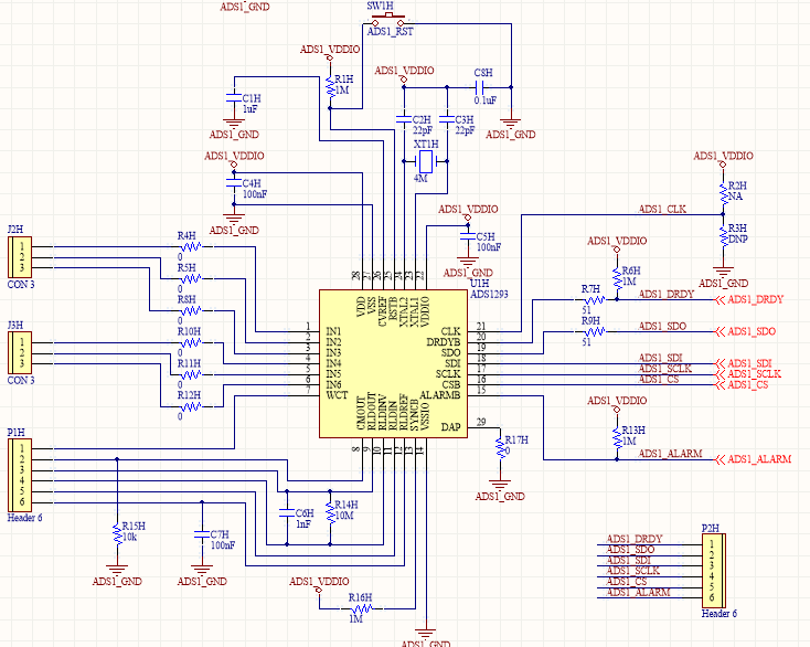
I decide to use ADS1293 and MSP430F6659. For ADS1293, I use external clock. From datasheet, I know that the Frequency of Crystal is 4.096MHz, but I cannot buy in Ho Chi Minh City, Vietnam. I have replaced with 4MHz crystal, and It's still not work. Any problem here?

I also attached my schematic below,

  • Hello A Do Tan and welcome to the E2E forum. Hey, and no problem, I can read you perfectly.

    This difference in the external crystal frequency should not be a problem such that the device does not work at all. Do you have the part number of the crystal that you are using? I can take a look at it.

    At first sight the schematic looks correct... the only error I could spot is R15H, which should connect from CMOUT to RLDINV and not to GND. But this should not stop the device from working, only the Right-Leg Drive circuit would not be functional.

    Can you probe with a voltmeter at these points:
    a) VDD and VDDIO... easier to probe at the capacitors C4H and C5H.
    b) CVREF should measure around 2.4V... probe at C1H
    c) RLDREF should measure around VDD/2.2... probe at P1H or C7H

    If these voltages are correct on your board then the analog side is properly powered.

    Can you read from registers? Try reading from address 0x40, which is the chip revision ID... the returned value should be 0x01.

    Can you write to registers? On power-up, the chip is in stand-by mode.Try writing to address 0x00... this register controls the state of the ADS1293.  If you are using a power supply with a current readout, playing with the values of this register would reflect changes in the current consumption of the chip. The values can be different because of the circuits that you connect to the supply may be different.

    Address 0x00 = 0x02 (default): Standby current is around 120uA
    Address 0x00 = 0x00:                Awake current is around 350uA

    If you can't measure the currents, simply try writing and then reading back the register to verify that the value you wrote is there. 

    Please let me know how these checks go and we can continue troubleshooting. Also, if you can give me more details of what does not work, that would be great.

    Thanks,

    Sergio

  • Thanks for your reply quickly.

    I just have proved as you said:

    VDD = VDDIO = 3.3V

    CVREF = 2.40V

    RLDREF = 1.49V

    So I think these voltage are correct.

    I try to read from address 0x00 and 0x40, the value return is always 0x00. Then, I write value 0x02 to address 0x00 and get back and it's also 0x00.

    I removed R15H and mount R 100k Ohm from CMOUT to RLDIN. but It's still not work.

    I attached my code below based on example code.

    Thanks for your helping me.3107.ADS1293Test.zip

  • It seems like the chip is powered up correctly. I am not familiar with the programming of the MSP430, so I can't help much on this regard. Have you probed with an oscilloscope on P2H to see if the SPI patterns expected are there?

    Can you attach the part of the schematic where the MSP430 is located?

    Thanks,

    Sergio

  • 3058.ADS1293_MSP430F6659.pdf

    Thanks for your response. My schematic is attached above.

    I checked MSP430F6659 and it worked OK. I don't have oscilloscope so I cannot capture signal from SPI bus.

    Thanks.

  • Oh, it's gonna be tough to know what is going on.

    Can you place a 100k or 1M pull-up resistor somewhere between R3L and pin 66 (SOMI) of the MSP430. I would like to see if your register read now returns 0xFF instead of 0x00 because of the pull-up resistor.

  • I don't know why but when I place a 100k pull-up resister pin SOMI to VCC, the value return is still 0x00. I think there is something wrong here!.  May be SPI mode of MSP430 have a problem. I'll recheck it.

    Do you have any idea?

    Thanks.

  • I would have expected the value to change to 0xFF if the SPI bus was reading correctly. I don't know what could be wrong.

    Regards,

    Sergio

  • Instead of 100k pull-up resister, I place 10k pull-up resister pin SOMI, now the value return is 0xFF. It's mean that SPI mode of MSP430 is OK.

    So I think the problem is not at MSP430.

  • Good to hear that. I hope the SOMI trace/wire is making a good connection to the chip. Try checking for continuity for every SPI line from the MSP430 to the ADS1293.

    You would still have to verify that the SIMO and CS0 are working, but it's hard without the oscilloscope.

  • Hi Sergio,

    I just have checked my SPI bus on MSP430F6659 with other device and It worked fine. ( I tested with CC2500), so the problem I think is at ADS1293. Tomorrow, I'll remove 0 Ohm resister in my circuit and connect manually. I'm hopeful of success.

    Thanks for your helping me.

    A

  • Hope that works.

    Regards,

    Sergio

  • Oh my god. The reason is at RESET PIN. I don't know but although I placed a pull up resister 1MOhm, and It's still 0V when I probe at RESET pin. It's mean that my ADS1293 is always at reset state, so that why it's not work. I replaced with 10k Ohm  resister and now it work OK.

    Thanks for your helping me again.

    Best regard,

    Do Tan A

  • Hey, good job! I'm glad it's working. 

    Regards,

    Sergio