This thread has been locked.

If you have a related question, please click the "Ask a related question" button in the top right corner. The newly created question will be automatically linked to this question.

Output ripple issue DAC1282

Other Parts Discussed in Thread: DAC1282, ADS1282, DAC9881

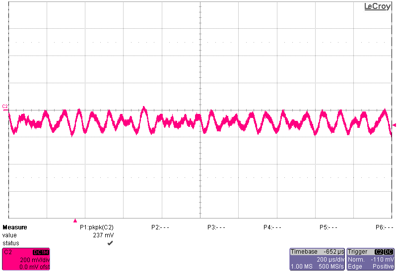
The output of the DAC1282 contains some pulse noise with frequency 256 kHz with amplitude of ~500mVp-p.

When the IC is power on there is no pulse noise, just a small sine wave which is logic due to the default settings. When initiating the DAC by writing hex 01 to register 0 the noise starts. Then the noise contains no matter what mode we commanding it to.  The screen shot below is showing the output signal for the DAC when commanding it to DC mode with 1.1V output signal, full range output (no damping).

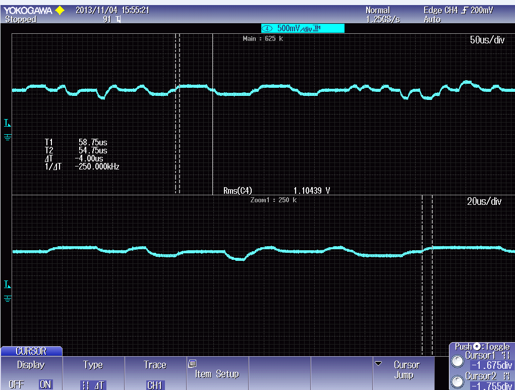
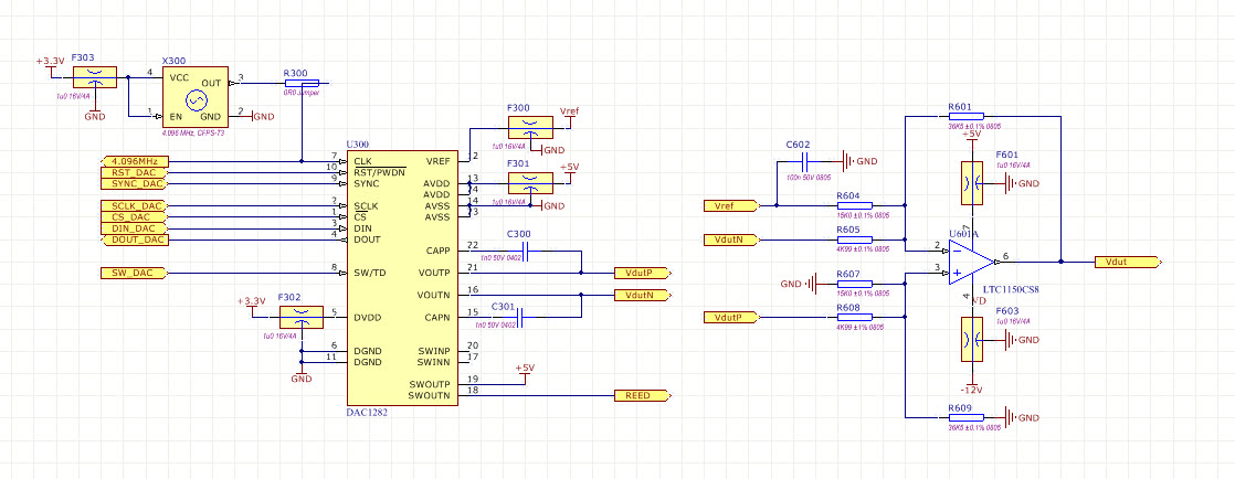
The DAC is connected to a difference amplifier and loaded with 5kOhm. The 1nF filter described in the datasheet is connected.

I feel like is it a quite simple error but I can't find it. Does someone have a solution for it?

/David

  • Hi David,

    Pardon the delay. Do you have a complete schematic I could look at?

    The DC noise with 0dB gain should be about 1.3uVrms. Where are you referencing the probe on your board? You might have a noisy ground. I could also take a look at your layout if you like.

    Best Regards,
    Chris

  • No worries, we have disconnected the DAC and uses a bench voltage supply from Agilent to be able to continue our measurements. 

    There is no such noise in the ground plane.

    It is a small board with linear power conditioning and one DAC and one ADC (ADS1282) together with four operational amplifier ICs. The data interface to both DAC and ADC is connected via optocoupler. The power supply to the different side of the optocoupler is isolated from each other. A picture of the DAC connections is shown below, if you need the complete design to find the answer maybe I can send it to you directly, 

    The output ripple is measured across the differential output. I have tried to increase the load but with no result.

    Regards David

  • Hi David,

    I missed a very important note in the data sheet of the DAC1282:

    (8) VOUT = 0 V. DC noise is measured by the ADS1282, over a 413-Hz bandwidth using complementing gain. DC noise is referred to a 1.77-V full-scale ADC output. Divide output-referred noise by the ADC gain to yield input-referred noise.

    The product definer confirmed that the noise on the DAC1282 output looks bad when viewed on an oscilloscope. I looked at it in the lab and observed 237mVpp:

    An important characteristic about the noise spectrum is that the higher frequencies contain the majority of noise, like the 256 kHz you're observing, which are out of band when sampled by the ADS1282. Recall the noise shaping effect that occurs with a delta-sigma modulator. Typically in a delta-sigma ADC, the modulator is followed by a low-pass filter to remove the noise and provide the high resolution digital output.

    When I sampled the DAC1282 with the ADS1282 at 1kSPS this is what I observe:

    Time Domain: (~1 uVrms which is in line with the DAC1282 data sheet)

    Frequency Domain:

    The SINC + FIR filter on the ADS1282 removes the out-of-band noise. The 256 kHz is the modulator clock frequency (CLK/16) and this frequency also corresponds to one of the SINC filter notches.

    In summary, the DAC1282 is specifically purposed for testing the ADS1282 for seismic applications which require the low-harmonic distortion. The DAC1282 is not the best precision low-noise DAC. I would point you towards the DAC9881 18-bit DAC for something like that. However, when you combine the DAC1282 and ADS1282 the noise is greatly attenuated.

    Best Regards,
    Chris

  • Thank you Chris!


    The output ripple you have seen with the oscilloscope looks very much like ours. Please update the Datasheet to avoid future misunderstanding. 

    The next generation design will have another DAC.


    Regards David