This thread has been locked.

If you have a related question, please click the "Ask a related question" button in the top right corner. The newly created question will be automatically linked to this question.

ADS 1247 Muxing

Other Parts Discussed in Thread: ADS1147, ADS1247

I'm trying to set up the ADS 1247 per figure 51 in the data sheet.

My setup mostly uses the defaults except for setting it to 2000SPS and turning on the internal refcon.

I am getting interrupts on my uController at 2K as DRDY goes low.  

If I do 3 8bit block bursts (spi configured to 8 bits) with the write data as NOP (0xFF), then it runs merrily along.

But, if instead I set the write bits to switch MUX to the other channel,  Its a long time before I get the next DRDY.

My write is

0x40  0x0 0x01

or

0x40 0x0 0x13

So... when I get the the interrupt, I drop CS, write the 3 values (the first 2 reads in parallel with the writes should be my 16 bit sample), raise CS.

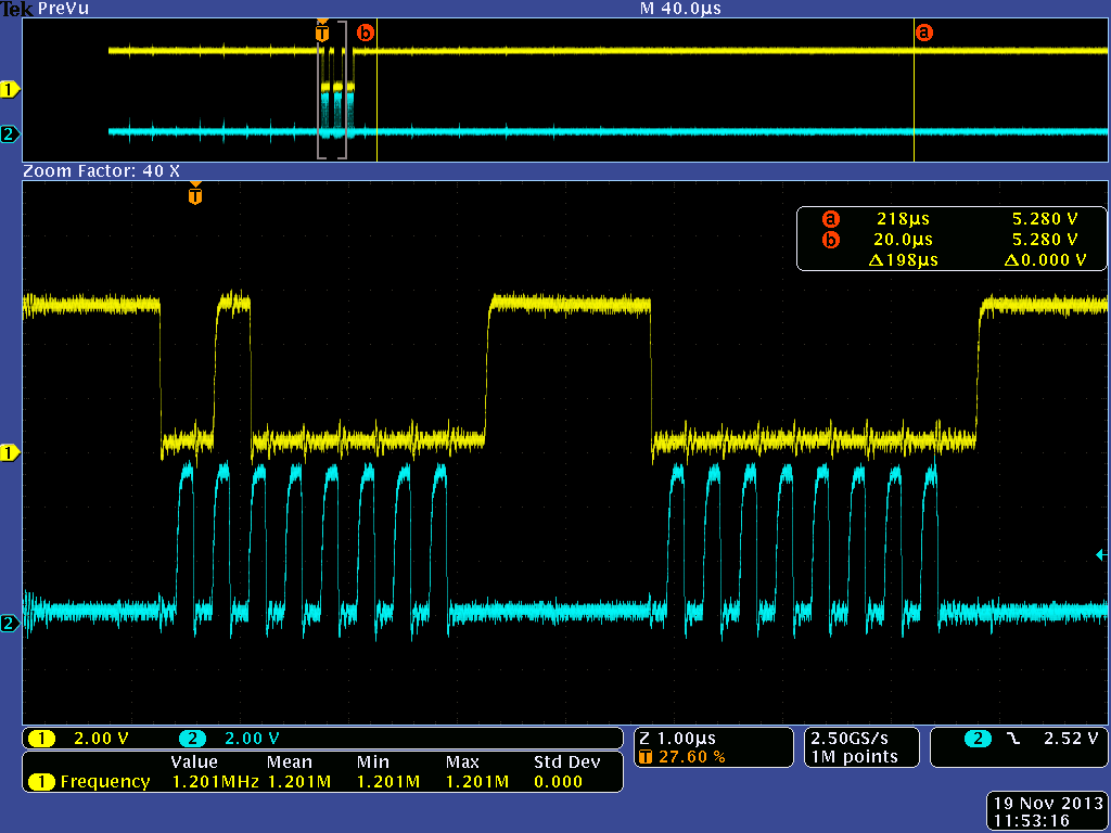
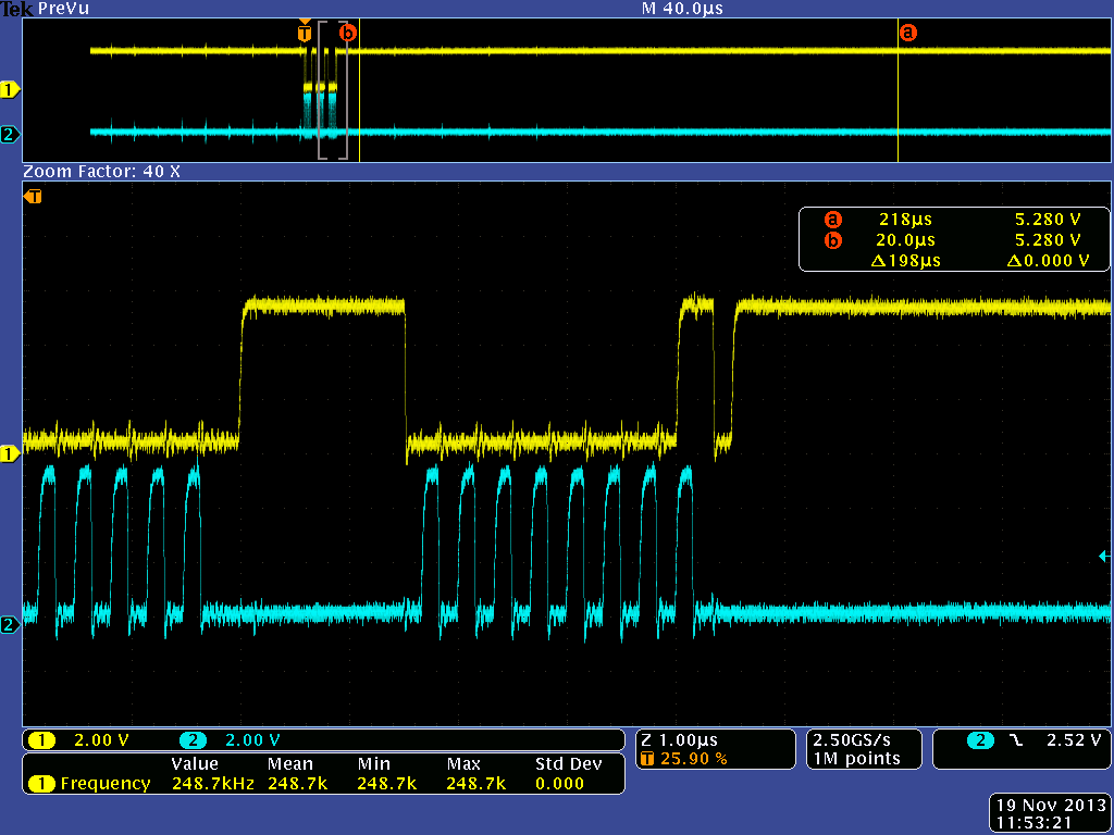
I see DRDY rise on the first write but its a long time till it goes down again, not .513 ms

ideas?

  • HI Matt,

    Welcome to the forum!  Are you using the most recent version of the datasheet?  Figure 51 is the device block diagram.  When you write to the register, the digital filter will reset at the conclusion of the register write.  The next DRDY should be very close to the 0.514ms shown in Table 16 (time starts following last SCLK after the register write).

    Can you send me some scope pictures of the write and length of time time  before DRDY falls?

    Thanks,
    Bob B

  • SBAS453F –JULY 2009–REVISED APRIL 2012

    Figure 51. SPI Communication Sequence for Channel Multiplexing

    Signals are attached

    ads1147_mux0.pdf
  • Hi Matt,

    Thanks for the info.  The thread title refers to the ADS1247 and the datasheet you are referring is for the ADS1147.  They are similar devices, but the datasheet is different for the two devices so that is my confusion.

    I don't see anything in the communication shots you sent that would create this type of delay.  One thing that could cause the issue is if the command is being misinterpreted.  This could be noise related to SCLK and the data in to the device.  As an example, the WREG might appear as SYSOCAL.  In your zoom in shot I missed the command and just see the data.  Can you send me that portion of the zoom in? Also, does the mux actually change?  Can you send me your schematic?

    Best regards,

    Bob B

  • Sorry... SBAS426G –AUGUST 2008–REVISED OCTOBER 2011

    Figure 83 on page 55

    Attached is the data image.  Got cut off when I converted my doc to pdf

    In this case it is writing to reg 0, byte count 0, data 0x1  for ain0/ain1,   The curious thing is that if I write 0x1 every time instead of every other time, the timing is still off. But if I write 0x13 every time (ain2/ain3) then I get a samples at the 2k rate.

  • Hi Matt,

    It looks to me that you are close or maybe over the maximum SCLK frequency.  Try slowing down the SCLK.

    Best regards,

    Bob B

  • Lowered it to under 1meg. Made no difference.  It appears that SYS0 is getting clobbered. If I read that after the first data is read, it has reset to 0, from 9.

  • Hi Matt,

    That is very interesting.  Do any of the other registers reset to default values?  Can you send me your schematic?  Maybe a code snippet?

    Best regards,

    Bob B

  • Can they be sent non-public?

  • Click on my name above the post and Start a Conversation with me that is private (link is in the upper right of the page.)

    Best regards,

    Bob B

  • I'm set Bob, thanks for looking at it.  It appear the issue is somehow related to reset. 

    If I load/run code via an ICD the issue occurs.  If I power cycle after loading code, then it is fine.  I'm guessing that its because the reset on the ADC is not tied to the microprocessor, but is just tied to its own power supply and resetting of the micro from jtag is getting the ADC's power in an odd state.  But who knows.