


Other Parts Discussed in Thread: DAC5682Z
Hello, My DAC5682Z work seems well in X2 model,but strange in X1 model.
The DAC5682Z is controlled by FPGA and the connection relationship is shown above.
The DAC5682’s output is connected directly to an RF transform without any filter, and finally to a SMA port. The data is given by FPGA from a ROM filled with data produced by Matlab. The data is QPSK shaping data with RRC filter. I test the output directly from SMA.
Next is image when DAC works on X2 mode.
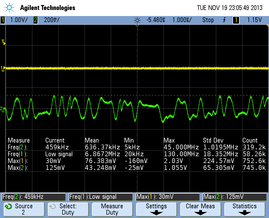
I am not sure whether DA is working right. Although it seems that the data has been treated, but there is some strange jump in the image. Right, this data is gotten with 1M coupling.
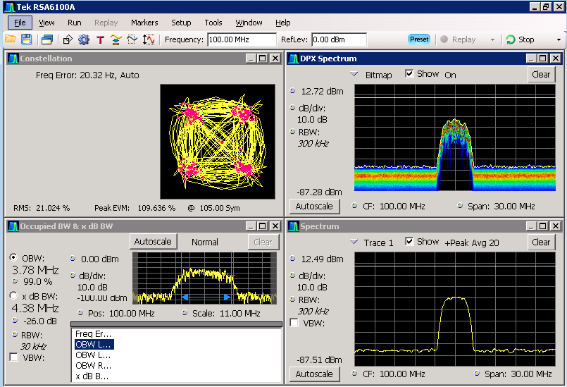
And next is the data analysis by spectrum analyzer. Under X2 mode, the symbol rate is 3.125M with 0.35 roll off, the bandwidth is nearly right.
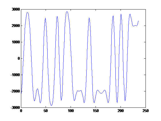
This is the data made by Matlab, Same as chipscope.
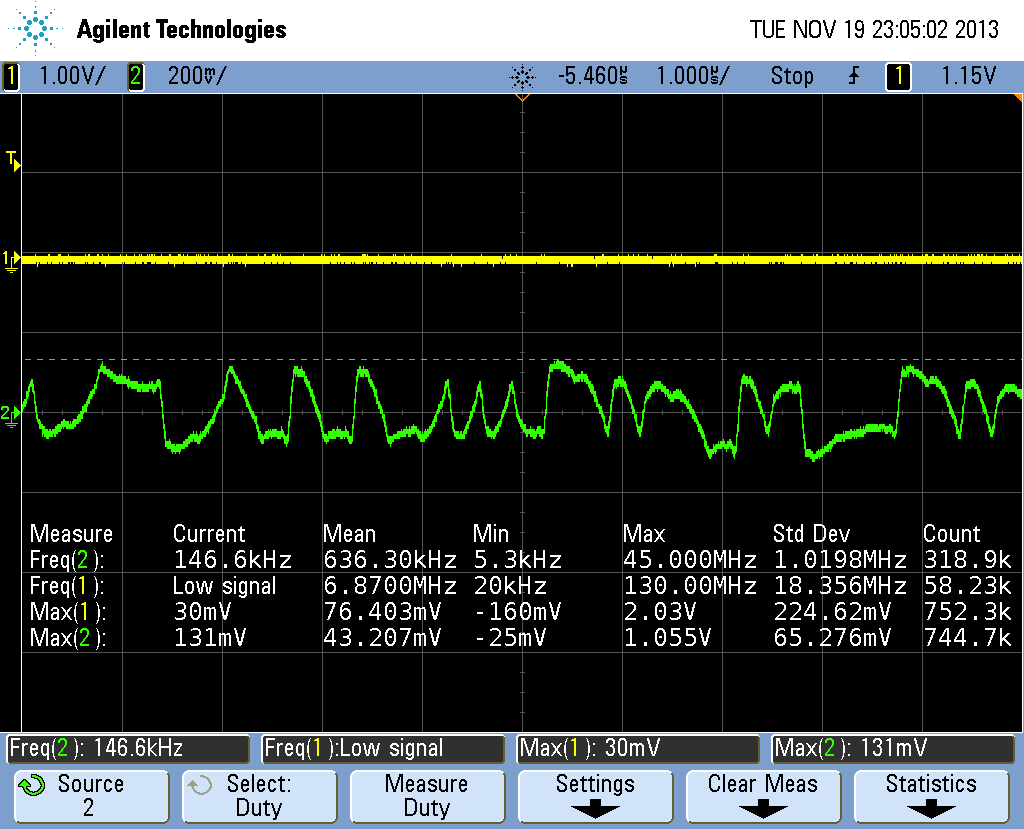
However the output while DAC5682Z works under X1 mode is wrong as shown above.
Also I test DA using pattern, eight 0xAAAA and eight 0x5555, so on…I do not have any pattern error but having fifo error all the time both in X1 and X2 mode.
Next is the image under X1 with 1M imped.
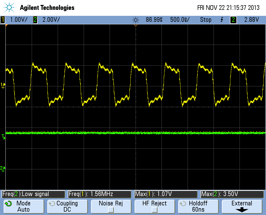
Next two figure is the image under X1 with 50o imped. Why they are different so much.
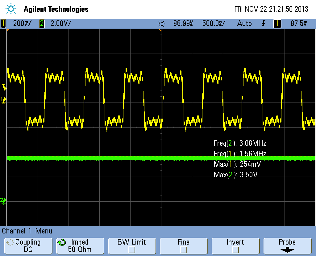
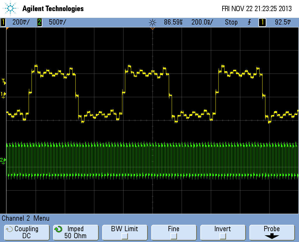
So I want to know whether DAC5682Z works well under X2 mode, and why it works strange in X1 mode.
Also I am confused with tS, tH (DCLK to Data) on page 9 of data sheet, it tells me that Hold_min is -600ps. Why it is negative? Does the negative number mean the data needed to be stable only for 1100ps-600ps= 500ps but not 1100ps+600ps=1700ps?
