This thread has been locked.

If you have a related question, please click the "Ask a related question" button in the top right corner. The newly created question will be automatically linked to this question.

DAC3482EVM

Other Parts Discussed in Thread: DAC3482

Hello,

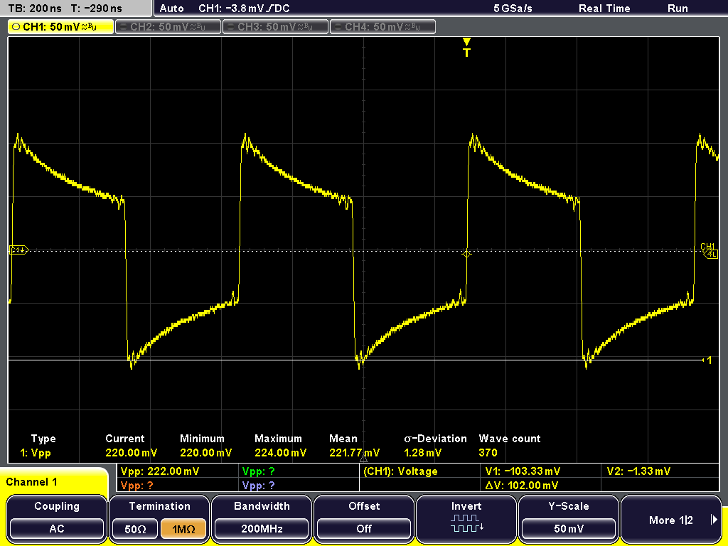
I have a bit stream of 1s and 0s. And I am making a digital signal out of it. If it is one I have some amplitude which is positive and if it is 0, I have a negative amplitude. Basically half of the csv file has 32767 as its value and another half as -32767. I load this file in the high speed data converter pro software and I see a square wave, which is shown in the attached file 'data_in.png'. I load this type of data into the DAC3482 and I observe some decaying waveform at the output, it is shown in the attached file "data_out.png". I would like to know why is the output not constant. I kindly request your help at the earliest as I am stuck with my project.

Thank You

Nikhil

  • Nikhil,

    The DAC348x EVM by default have transformer coupled with a bandpass response. This is the reason that you see transients being passed through the transformer but not the final DC value being settled. 

    For proper square wave output, you will need to terminate the DAC resistively. You may do so by connecting 25ohm load to positive and negative leg of the DAC output. Refer to the EVM schematic for the zero ohm jumper options and path needed to do so. 

    Refer to the following app note for details of DAC output analog interface:

    http://www.ti.com/litv/pdf/slua647a

    -Kang

  • Hello,

    Thank you for the reply. I will go through the document and see what I can do. In the mean time I have one more question. I need to send random bits of data from the PC. So I use MATLAB to do modulation. I first generate a carrier of 50MHz in Matlab. And I look in to my bits and If the bit is '1' a carrier with amplitude =1 is transmitted and if the bit is '0' then a zero is transmitted. I am doing some kind of ASK here. So when I see the output of the DAC I can see the modulated waveform, but this waveform repeats. I see this waveform in the oscilloscope, and I use the oscilloscope to get the samples. When I see these samples, the modulated waveform repeats. So how do I decode the data if the waveform is repeating? 

    Could you please help me in this regard?

    Thank You

    Nikhil

  • Hi,

    The TSW1400 will repeat the pattern in the memory at all time. You may need to construct some sort of pilot signal in your data to understand the start of the pattern.

    You may also use SYNC4 output (at J17 connector). This output will generate a high pulse everytime the pattern repeats from the memory. You may use this signal to gate the capture.

    I can't provide much more information since this is more towards system related questions rather than data converter support questions. Good luck. 

    -Kang