This thread has been locked.

If you have a related question, please click the "Ask a related question" button in the top right corner. The newly created question will be automatically linked to this question.

Incorrect readings from the ADS1110

Other Parts Discussed in Thread: ADS1110, LMC662

Hi,

I am using the ADS1110 via the I2C protocol to read voltages coming from an OP AMP (LMC662), but I noticed that the result is constantly 0.2V, which is incorrect, while the results coming from the analog pin of my microcontroller are correct. The ADS1110 will read voltages from a 10k ohm potentiometer just fine so I know it is working. Therefore, I assume it is a high output/low input impedance issue so I tried inserting a buffer in between the OP AMP and the ADS1110 but the buffer somehow amplified the voltage to 1.6V. The OP AMP I am using as the buffer is the LM324N.

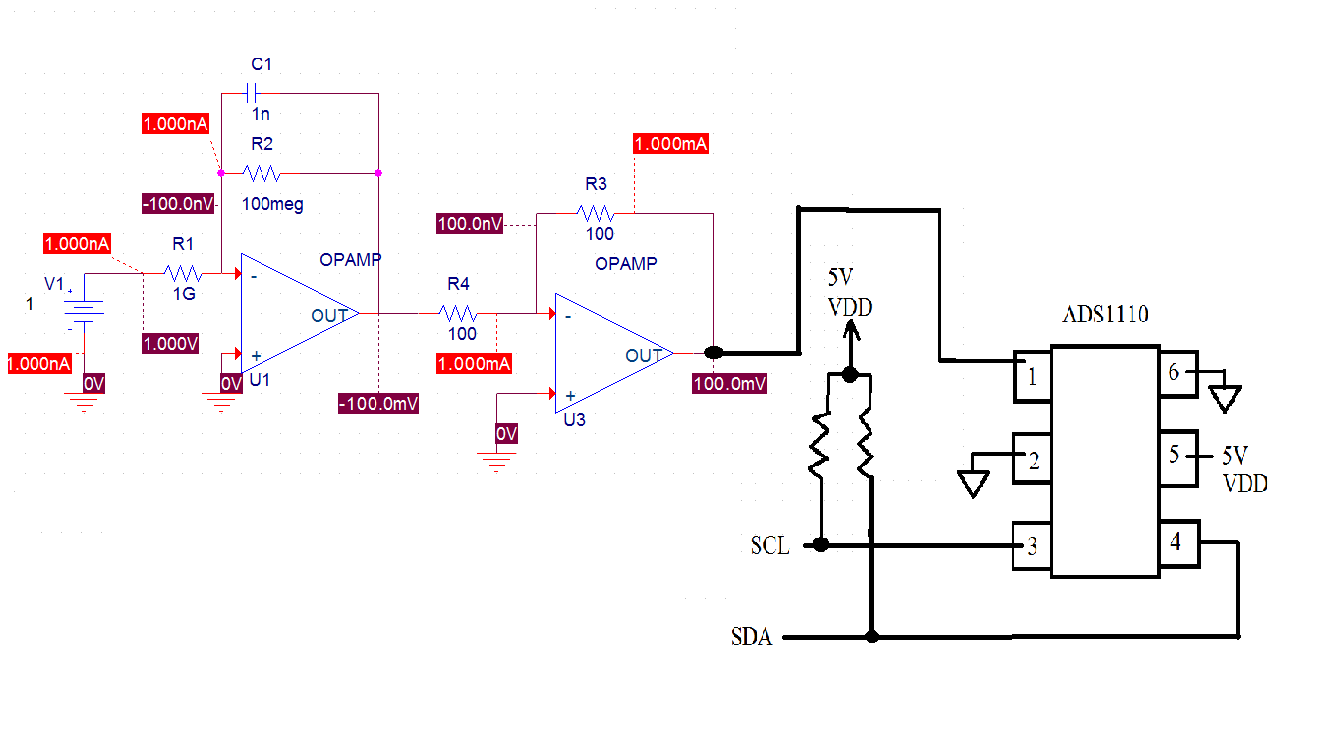
Here is the schematic

I am not sure where to go from here.

Regards

Bunnarong

  • Hi Bunnarong,

    I'm not sure what you are expecting to see with the circuit as shown.  If you consider the virtual short of the op amp between pins 2 and 3, with the positive input grounded, pin 2 will always be near ground.  This makes the buffer op amp to never see the input value.  The buffer op amp should be connected to the output, pin 1, of the previous stage.  However, the output will always be below ground as the op amp will be in the inverting configuration.  This configuration will damage the ADS1110.

    You also have very large resistors that may affect the overall perfomance.  If about 1V is dropped across R1, this would be a current of about 1nA, which is in the range of the bias current of the op amp.  In the configuration as you have it, this current will be divided between the op amps, and the output uncertain.

    For this to work, you will need to place the first op amp in a non-inverting configuration, or you need to make the second stage another inverting stage so that the output is above ground.  I would suggest that you simulate your configuration to make sure the response is how you would like to see it prior to actually building it.

    Best regards,

    Bob B

  • I have made the corrections you have suggested and simulated it. The output of the first is negative so I used a second OP AMP as an inverter and buffer. Unfortunately, both the microcontroller and ADS1110 are outputting the same wrong result, which is ~1.2V, but I expected to see 0.1V. I have two other ADS1110 and both of them show the same result (~1.2V). Additionally, this value will not change or show an sign of response with respect to V1.

    Thank you for taking the time to reply,

    Bunnarong

  • Hi Bunnarong,

    It would seem as though the input is floating.  Make sure you have good ground connections between the op amp circuit and the ADS1110.  Pin 2 and pin 6 of the ADS1110 must have the same ground potential (or common point) as the op amp circuit ground.

    Best regards,

    Bob B