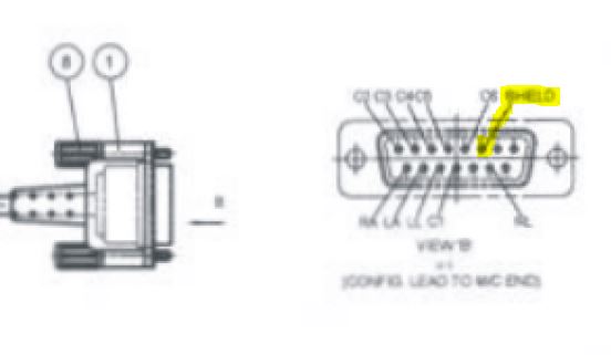
I am looking closely at the schematic contained in the ADS1298ECG-FE User Guide (SBAU171C). This is a demo board for the ADS1298 ECG chip. I am a bit confused on the driven cable shield signal. The idea is to invert the RLD signal and drive the cable shield that attaches to the board via a 15 pin DSUB connector. OK, makes sense. The schematic shows the ECG_SHD_DRV signal going through a jumper where it becomes ELEC_SHD (jumper choice is to use either GND or ECG_SHD_DRV for the shield). Then, strangely, the ELEC_SHD signal ties to pin 6 of the DSUB connector(!?) Is that correct? Why would it tie to pin 6? Is this a special cable arrangement where the specified cable (from Biometric Cables) ties the cable shield to pin 6? I am prototyping an idea and would like to use the Biometric Cable. I just need to know how to properly handle the driven shield signal. Thanks in advance for any insight into this issue. Have a great day!
Gary