This thread has been locked.

If you have a related question, please click the "Ask a related question" button in the top right corner. The newly created question will be automatically linked to this question.

Can't get ADS1248 source current use EVM.

Other Parts Discussed in Thread: ADS1248, ADCPRO

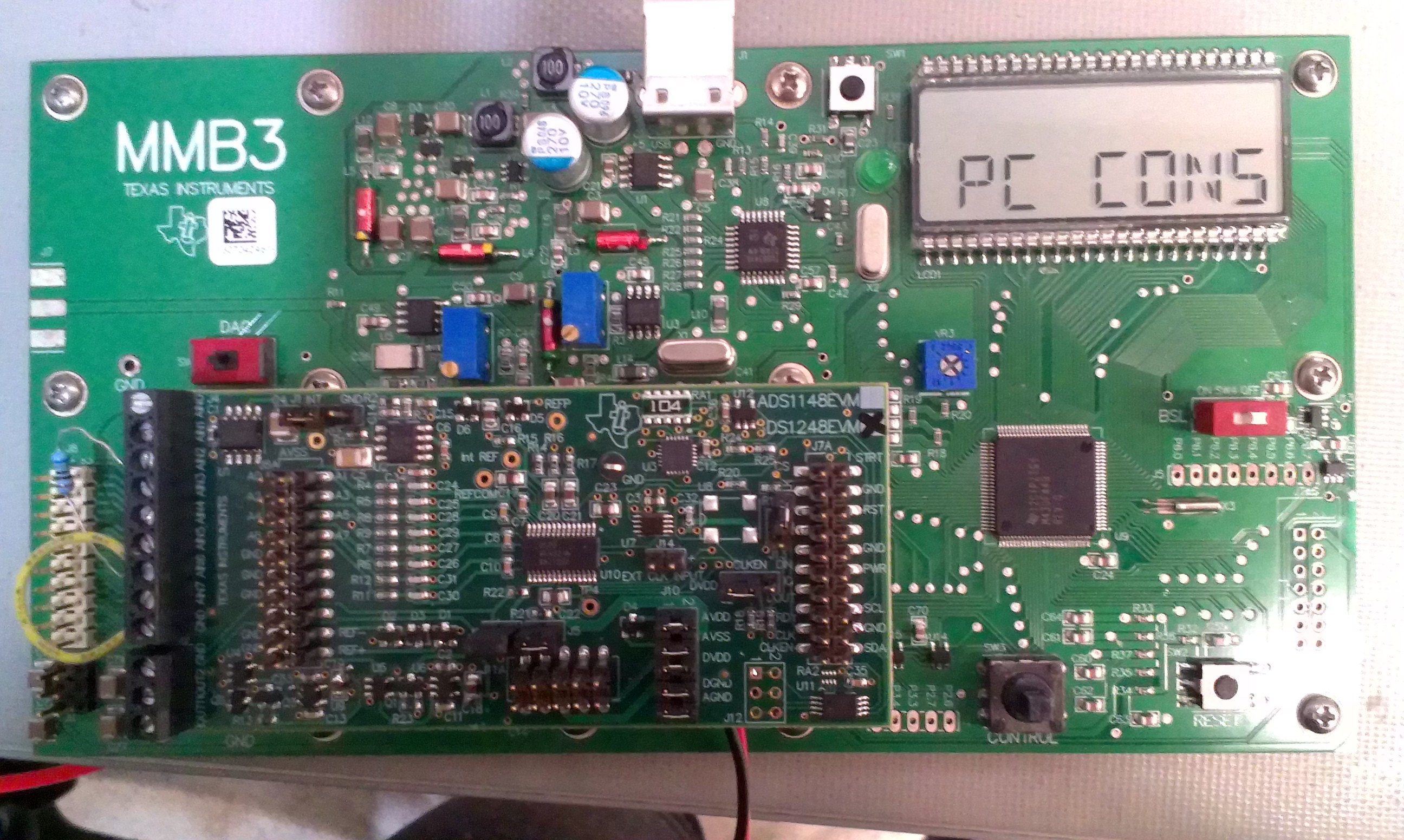
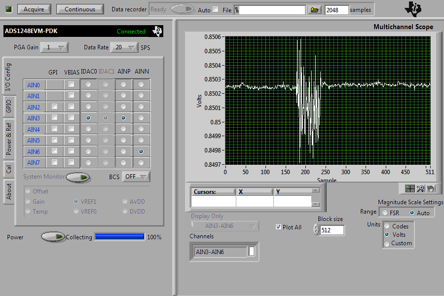
Hello, I want to test ADS1248's source current mismatch, the test circuit and ADC Pro configuration is as below.

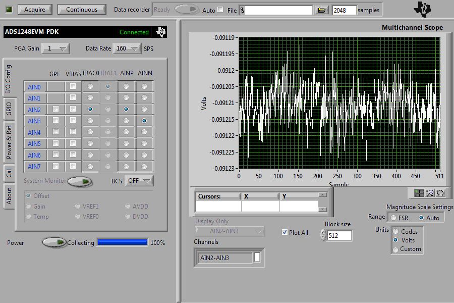
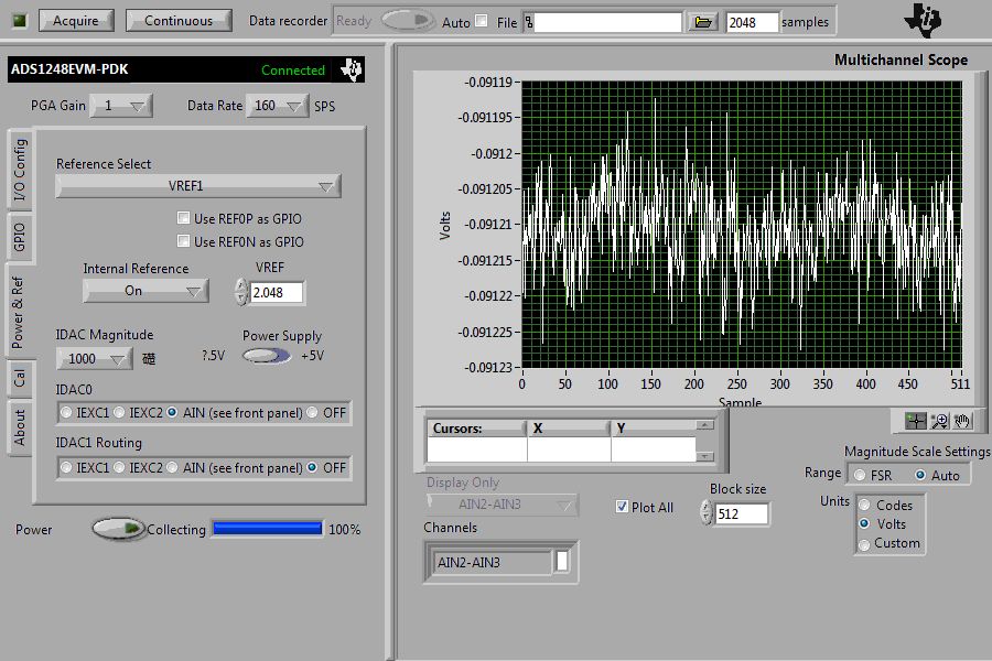
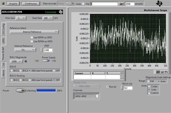
You see with different source current, the output voltage are the same. use multimeter to test the voltage on the 680Ω resistor , the showed voltage is nearly zero, even if I change the source current. Why? is there something wrong the ADC Pro setting. Thank you. 

  • Hi Nicole,

    I would verify that the +/-2.5V supplies are working correctly.  I would also double check and make sure that you have a good connection where the resistor connects to the terminal block.  I suspect that there is a setup or connection problem.  Also, there is an issue with how you are making the measurment.  There is a 47 ohm filter resistor in the current path.  This resistor will have some drift and add some noise.

    The best way to use the ADS1248EVM is to use the external IDAC connections.  This is on the J9 terminal block as can be seen in the User's Guide schematic.  There are also resistors in series with these outputs (R21 and R22) but can be bypassed by connecting the jumpers at J5 and J6.  So connect a wire from the IDAC terminal block to the AIN2 input and also add the resistor to the AIN2 input.  The other side of the resistor should connect to AIN3, and also to the ground on the terminal block.  Make the appropriate settings in ADCPro.  One other thing you should also do is issue the SELFOCAL on the Cal tab of the GUI.

    On the ADCPro Power and Ref tab, instead of selecting the AIN (see front panel) selection choose the appropriate source (IEXC1 or IEXC2) depending on how you connected the two terminal blocks together.

    If you are still having problems you will need to make sure all of the necessary voltages are present.  Besides the +/-2.5V for AVDD and AVSS you should measure externally across the resistor and you should see aproximately 680mV for a 1mA of IDAC current.

    Best regards,

    Bob B

  • Hi, Bob,

    Thank you for replying. I did test as you suggested, but still not work.

  • Hi Nicole,

    I verified the operation on my ADS1248EVM before I responded previously.  This means that there is either a setup issue, or an issue with the EVM itself.

    Can you send me a picture of the EVM as it is connected using your setup?  Also, make sure that the DAC switch on the MMB3 is in the OUT position (red colored switch on the left-center of the MMB3).

    Thanks,

    Bob B

  • Bob,

    Thank you very much. Now I made the DAC switch on the MMB3 to left, and got the voltage drop on the resistor, and it did change with the exciting current, while did not equal to Iexc*R. the following picture is EVM connection and ADC pro setup. Thank you.

  • Hi Nicole,

    After reading my previous post I realize I was unclear about how to set the switch on the MMB3.  The DAC switch (SW5) must be in the OUT position, which means the switch should go to the right.  We do not want the MMB3 DAC to be driving the input.  The default output for the DAC is 5V at the Ain0 input.  When running the ADS1248EVM at +/-2.5V, the 5V input will create excessive current flow through the input pin conducting through the ESD diode and can potentially damage the ADS1248.  It could also be the source of the additional current you are seeing.

    As I stated earlier, with this configuration you will also see an additional voltage drop added by R7.  It would be better to direct the current out the J9 terminal block with a short wire to the AIN3 input so that you bypass the input filtering.

    Another consideration is that there is no differential filter caps between AIN3 and AIN6 on the EVM.  The tolerance difference in the common mode filters may also add to the noise and create a differential voltage between the inputs.  The EVM has the inputs grouped in pairs. AIN0-AIN1, AIN2-AIN3, AIN4-AIN5, and AIN6-AIN7.  You should be using one of the input pairs for the measurement.

    Best regards,

    Bob B