This thread has been locked.

If you have a related question, please click the "Ask a related question" button in the top right corner. The newly created question will be automatically linked to this question.

ads7953 SPI data issue

Other Parts Discussed in Thread: ADS7953, ADS7960, ADS7961

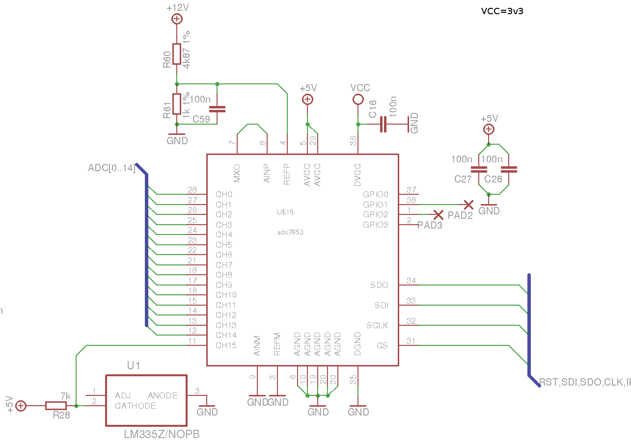
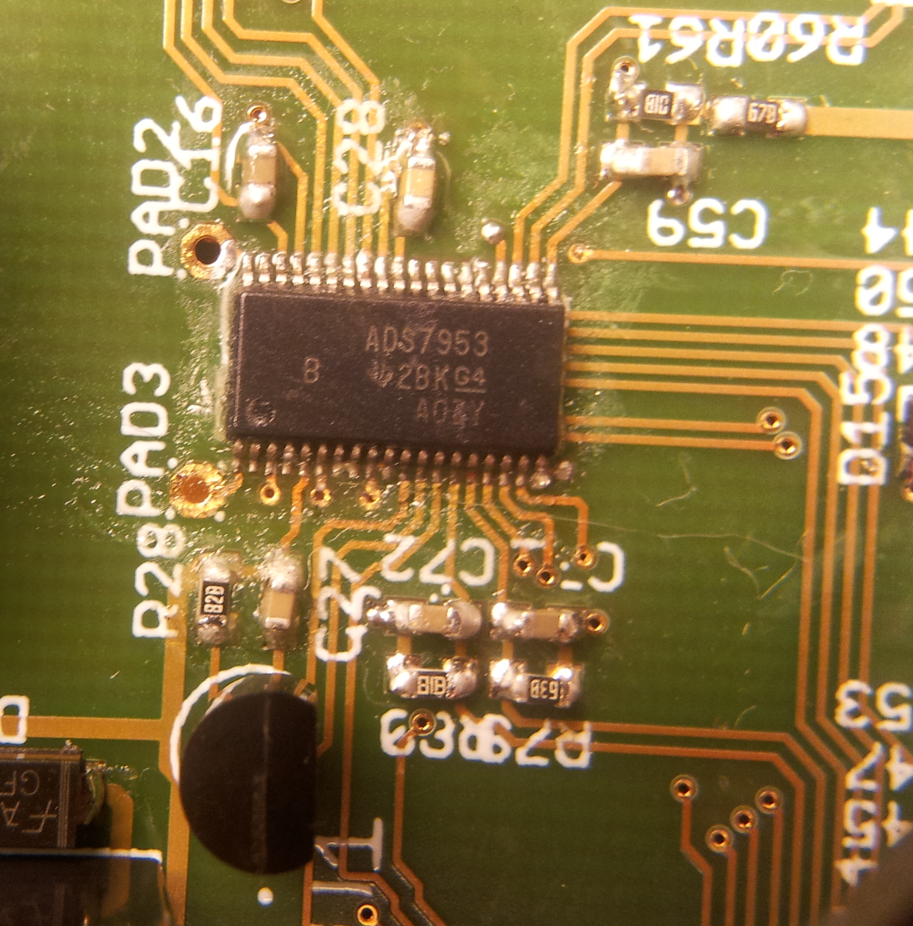
I am currently working with an ads7953 on my new prototype board and I came across a strange issue when talking to the chip.

The ADS chip responds normally to my calls in manual mode only 4 LSB bits keep asserted at all times.

I came across this when I was measuring my temperature sensor on channel15.

I put some cold spray on it and the general temperature started to fall, only to notice that the lower 8 bits always stayed 0xf.

 a sequence of raw data packets I received from the ADS are this (after applying cold spray)

f85f
f87f
f88f
f89f
f8af
f8bf
f8cf
f8df
f8ff
f8ff

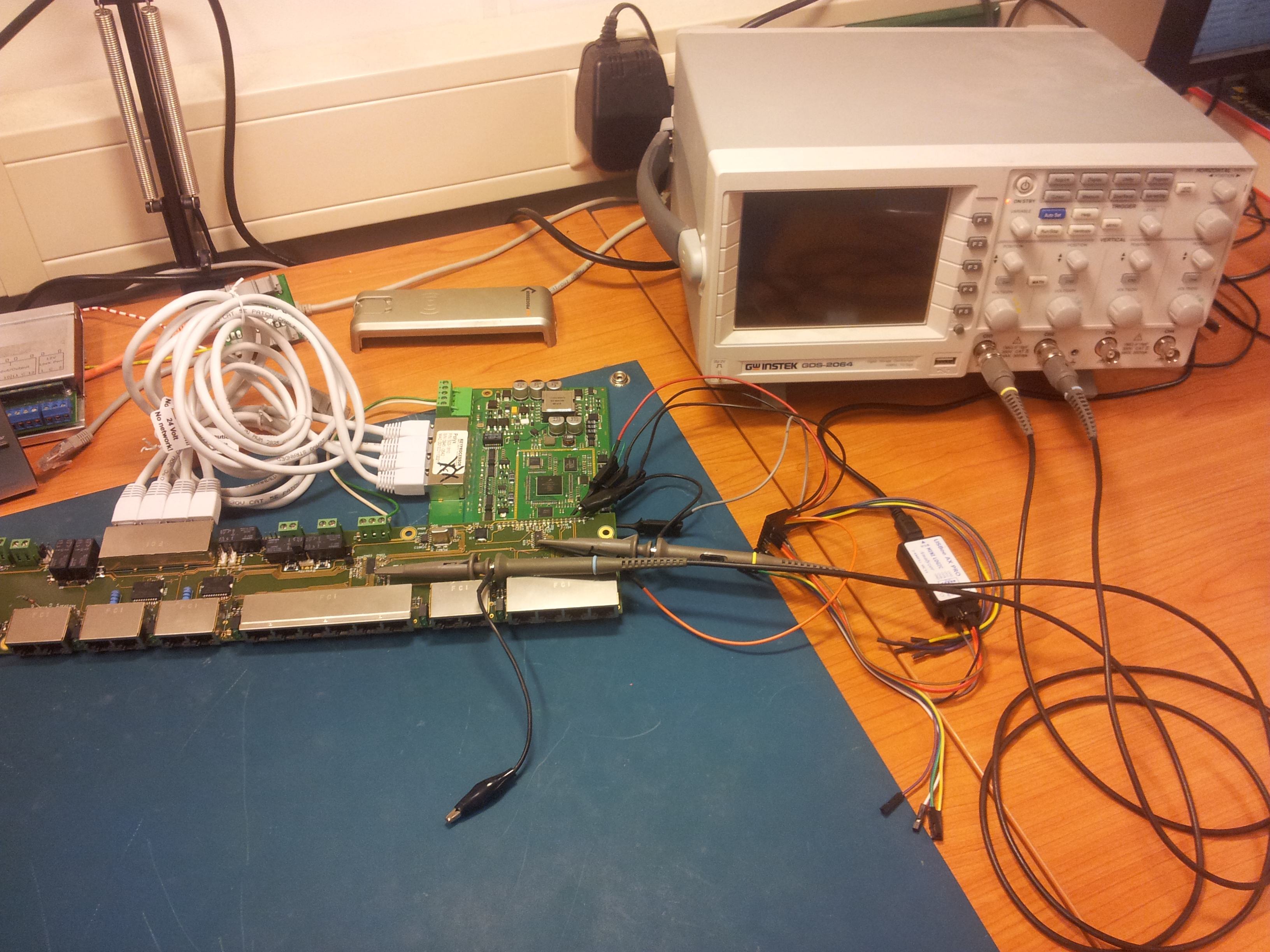
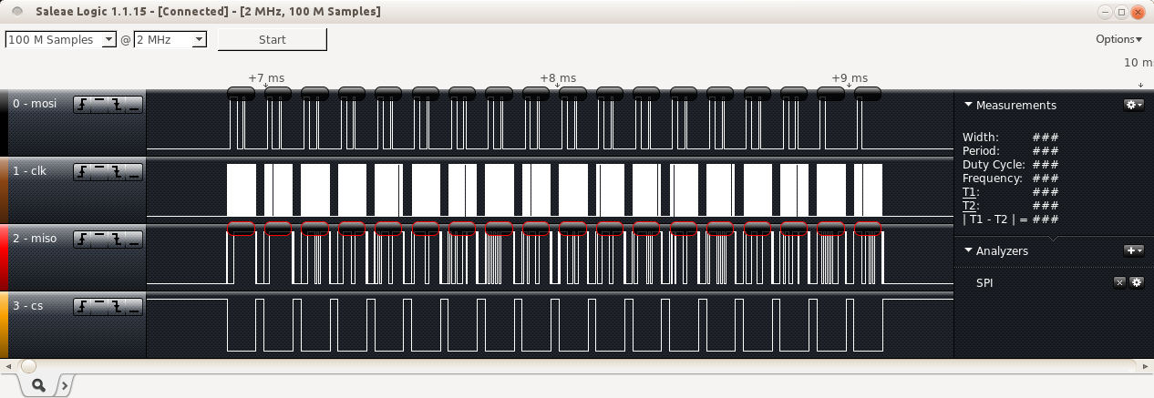
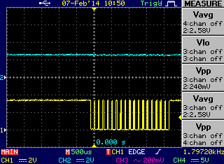
I was pretty confused by this output, so I hooked my logic probe to the SPI but only to see that the values reported in my program were the actual values reported by the ADS chip.

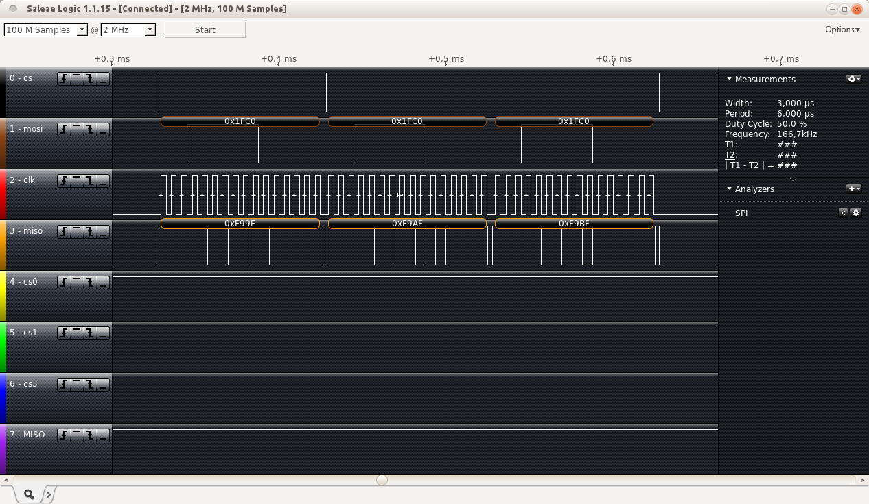
The SPI baud rate is also by a long way to be called slow with 166khz...

I am really baffled by these results.

Does anyone perhaps have a hint to what I am doing wrong?

Thank you

  • Sebastiaan,

    Thank you for your interest in the ADS7953.

    The observation that you have captured in your mail is indeed strange. Could we start by ruling out the obvious errors:

    1. It might be possible that the temp sensor you are using does not have enough drive to charge the sampling network. Which temp sensor are you using to drive the ADC? Is there an driving amplifier in between the two? Could you share your schematics for us to study?

    2. Could you check whether you have accidently mounted an 8-bit ADC from the same family – the ADS7961 or ADS7960 maybe? This might explain why we are seeing only 8-bits toggling and the last 4 bits stuck at 0xF.

    Looking forward to your response.

    Regards,

    Sandeep

  • Hello Sandeep,

    Thank you very much for your responce.

    The sensor I use is an LM335z with an 7k resistor on the cathode.
    If you want I can email you the schematics, but maybe this snapshot is sufficient.

    I want to state here that after investigations all channels report always 0xf as LSB's.

    So the issue seems to be confined to the ADC itself.

    The chip markings was one of the first things I checked before posting on this forum.
    the exact markings are:

           ADS7953
    B    (ti) 28Kg4
                  AOZY

    An picture of these markings:

    Again Thank you very much for your help.

    Regards,

    Sebastiaan

  • Sebastiaan,

    The logic analyzer capture of your SPI interface seems correct. The waveform does not show the second CS high pulse, but I am guessing this is a LA capture issue.

    However looking at the schematic snapshot, it appears that the Vref is derived directly from a power supply using the resistor divider and changes in current can impact this voltage. Ideally, the REFP pin should be driven with a stable +2.5V (for Range 1 operation) derived from a reference IC such as the REF5025 as described in page 42 of the ADS7953 datasheet.

    Just to confirm that this is the source of the 0xF on LSB behaviour that we are seeing, could you try observing the REFP pin on an oscilloscope along with the SCLK? The device internally switches modes as it evaluates each bit and at the 11th falling edge of SCLK you should see a dip in the voltage at the REFP pin. This dip would explain why the last 4 LSBs (driven on clocks 12th to 15th) are coming out as 0xF.

    Regards,

    Sandeep

  • Hello Sandeep,

    I made some measurements for you , but to start with , when the Vref is not stable I would at least suspect the LSB's to be random, The MSB's in that case wouldn't be random....

    I put my system in auto mode for this measurement, with every 10ms a full scan of all 16 channels.

    My setup is like this:

    The data what has been sent and received according the logic probe:


    And this is the data from my scope, channel 1 is the CS and holds a trigger channel 2 holds the Vref :

    I hope we can solve this problem.

    Sincerely,

    Sebastiaan

  • Hello Sandeep,

    Are there any additional measurements I should make to help you diagnose this problem?

    sincerely,

    Sebastiaan

  • Sebastiaan,

    I tried modifying an ADS7953 tester board here to setup the reference the way you have it on your board. As expected, the conversion results came out bad. However, I am not able to get the last nibble stuck at 0xF. I currently don’t have a clear experiment to explain that behaviour.

    Nonetheless, the reference on your board needs to be fixed. For the ADS7953, the LSB = Vref/(2^12-1) = 2.5/4095 = 611uV. With a resistor divider to derive the reference, the actual voltage that the ADC uses for its comparisons would vary based on small shifts in the load current and impact the output codes. It is recommended to drive the REF pin with a low noise reference like the REF5025, as mentioned in page 42 on the datasheet.

    Regards,

    Sandeep