This thread has been locked.
If you have a related question, please click the "Ask a related question" button in the top right corner. The newly created question will be automatically linked to this question.
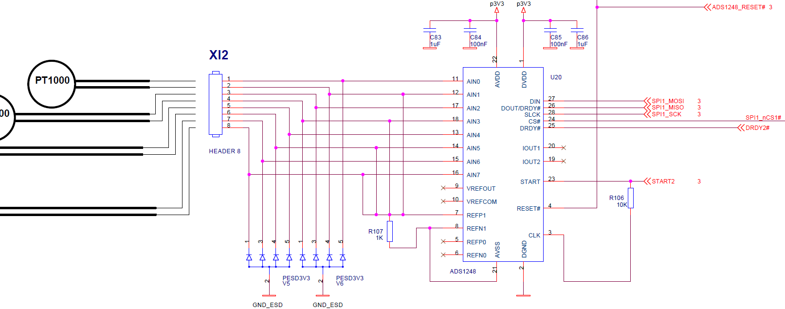
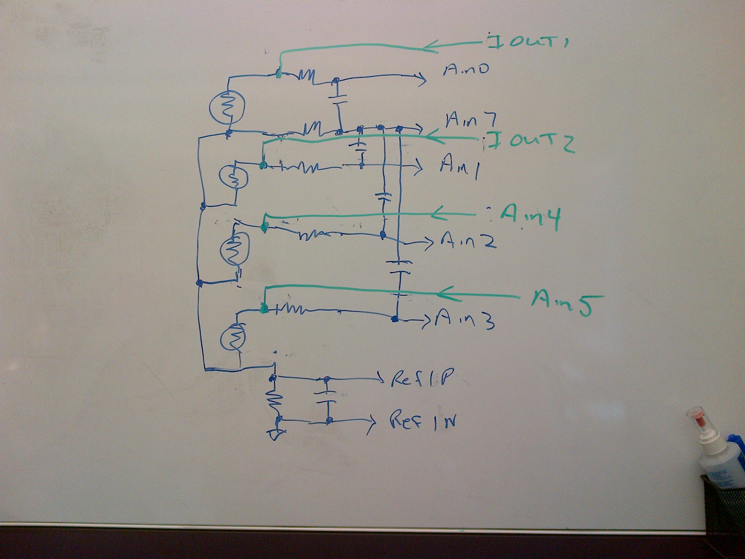
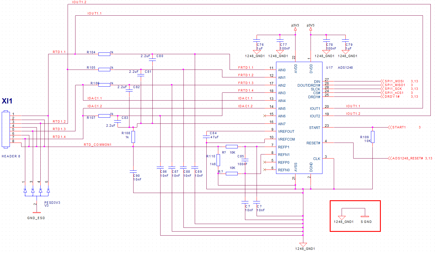
I need a check and a confirmation for the design here below, where I use an ADS1248 to read 4 RTDs (PT-1000, 2-wire).
The temperature measurement range is -20ºC to +150ºC, so probably the resistor across REF1 (now with 1k) will be better 1k8 to work in full range. PT-1000 have a very short connection (less than 2 meter).
Thanks
Hi Paolo,
There are many possible combinations for connecting the RTDs. One thing to consider is you have no input filtering, only transient protection. You should have filtering for at least for anti-aliasing. Also consider that 2 parallel wires for even a short distance will act as an antenna adding EMI/RFI issues. The problem with adding input filtering, using the method and design proposed, will be the additional error of the current running through the input filter resistor into the measurement. This can be removed by supplying the input current on the input side of the filter. With the schematic at present, the only available pins for supplying current are from the IOUT1 and IOUT2 pins. If you alter your configuration you can have 4, 2-wire RTDs connected by using the analog pins in a different way. For example, you could use AIN7 as a common for all devices and would be the AINN input. This would also connect to the reference/bias resistor R107. This would allow connections for 4 RTDs to connect AINP to AIN0 through AIN3. This would leave the 3 remaining analog inputs available to source the current. This leaves 5 possible sources for current to be routed to the RTDs allowing an input filter to be added effectively. Also consider adding an input filter to the reference input as well, and review the application note SBAA201.
Some other things I noticed in your schematic. To use the IDACs you must turn on the internal reference. This requires a capacitor (1uF to 47uF) to be added across VREFOUT and VREFCOM. VREFCOM should also be connected to AVSS. Also AVSS should be connected to the supply ground (as well as REF1N and R107). Another missing connection is the CLK pin to ground.
It would appear that you intend to use 1mA for the IDAC current. You could use a smaller current (to reduce RTD self heating) and a larger reference resistor. In this way you can take advantage of the PGA gain. In any case, the reference resistor should be a precision resistor with low drift characteristics. You must also make sure that the measurement range is within the correct common mode range of the input and that you also maintain the IDAC compliance voltage requirement. Basically IDAC compliance means that the total voltage drop developed from the IDAC source must be less than AVDD-0.7V.
Best regards,
Bob B
Hi Bob,
thanks for the nice answer. This was my quick draft initial design for an RTD (PT-1000) intrface. I am obliged to use 2-wire PT-1000 since this is what customer wants I will study your suggestions. Can you address me to some suitable schematic(s) which I can better study? I did not find any suitable good example for getting hints to solve my problem.
Question: why you say that only IOUT1 and IOUT2 can be used as excitation current sources?
Isnt'it possible to connect (internally) the IDACx to any of the AINx pins of the ads1248?
Thanks
Best regards
Paolo
Hi Paolo,
I think you should re-read my previous post as it appears you have missed the point I was trying to make. As I said before, you can use your schematic design and the IDAC current source routing as you have it. However, there is no input filtering. Adding input filtering will cause an error when using the IDAC routing as you have it in your design. Also, 2-wire RTDs will have an error as you add the lead resistance to the measurement. It may be a small error as compared to PT100, but it will be a factor when measuring as the lead resistance will add to the PT1000 itself. Adding any additional resistance will also add to the error. You can design your system without input filters, but I can tell you that you will not be happy with the results. The design goal should be to limit the error and control the noise so that it is at a minimum.
If you wish to add input filters to reduce noise, and if you want to minimize the error that would be created by current flowing through the input resistor, then you must source the current independent to the analog input being measured. Your schematic configuration only has two available sources to do this. I recommended changing your schematic to minimize noise and error.
So to answer this last question, yes you can source the IDAC current through the IOUT1, IOUT2, or out any of the AIN0 through AIN7 pins.
The above example only shows differential caps, but common mode filtering caps could also be added.
Best regards,
Bob B
Hi Bob,
yes I was a bit out of synch due to time skew; I read your email late night, and probably I had to wait this morning to answer properly!
You are right, using both external and internal excitation current sources available from the ADS1248 and following your suggestions I can have a much better and stable result. Internal IDACx will flow out from Ain4 and Ain5.
I will use 1K/2.2uF filters which worked very well when I used the LMP90079 with "K" TC in another project, and also 10nF caps from each Ainx to the analog ground.
Since the required range will reach 150ºC degree up, which means the PT1000 would become 1577.7 Ohms, I was thinking to use 1.6k resistor between RefP and RefN to work in full range.
Have a look to the revised schematic here below. What do you think?
My best regards
Paolo
Hi Paolo,
This is close to what I think it should be, however I would move the common mode caps (the ones to ground on the analog inputs) to the other side of the input resistors so that there will be some filtering.
You may also want to add filtering to your reference inputs. Even though the SBAA201 application note is based on 4-wire RTDs, the concept for matching for the ratiometric measurement is the same.
Best regards,
Bob B
Hi Bob,
your help is really valuable. I have added the suggested modification to the schematic. Have a look.
Today the end customer asked for an additional feature: RTD (PT-1000, 2-wire) will not be 4 for each ADS1248, but one of the RTD interface blocks built around the ADS1248 will have 3 x PT-1000 and one PTC used to sense the overheat of a motor. This PTC is nominally 100 Ohm then rapidly raises up to 10K and over for motor overheat at the PTC selected characteristic temperature. I am not asked to measure the overheat temperature value but just sense that the motor has gone overheated. So I expect to have an out of scale readout from that PTC channel. Eventually I can program the IDAC current for that PTC AIN input differently from the other channels connected to the PT-1000. Am I wrong? This should be, hopefully, the final requirements. Thanks for the help. Schematic attached.
Last question: you suggested to use REFP1/REFN1. Why these and not the REFP0/REFN0? Just choice or is there any special reason?
Thanks and Best Regards
Paolo
Hi Paulo,
That configuration looks to be ok, but you may find that different component values may be desired for best ratiometric matching. Also, if you are to use 3.3V for the analog supply, you must make sure your design will provide enough margin for IDAC voltage compliance. If you use 1mA for IDAC current, you will not have enough margin throughout your measurement range. Please re-read my first response regarding IDAC compliance voltage.
When using a thermistor, the approach is similar. A 10k resistance response will cause some error as you will be outside the IDAC compliance if you use the same settings as you do for the RTD, but you should read a full-scale response for any voltage created larger than the reference. Normal operating conditions should be fine.
Best regards,
Bob B