To whom it may concern,
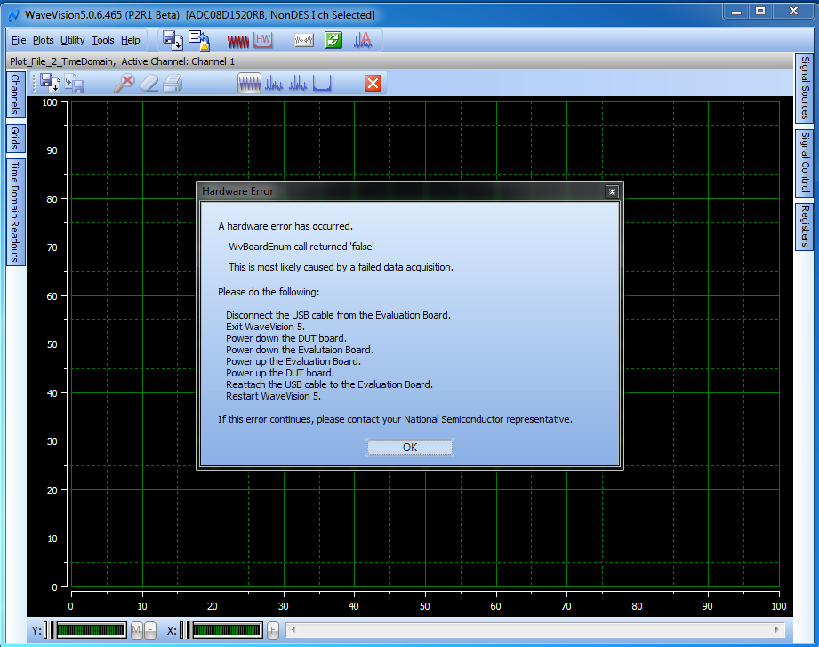
This is Bridget, a new user of Texas Instruments ADC0XD1520RB reference board. We found that the reference board we have is unable to be detected by WaveVision 5 running on a 64-bit windows 7 computer. Thus, to locate the root cause and conclude if the board is able to function, I would like to confirm with you a few points.
- To ensure SPI control of the ADC, we want to confirm the location of the LOW position for the ECE (Extended Control Enable) jumper to connect to, position 1 or position 2?
Position 1:
Position 2:
- Before WaveVision 5 loading the FPGA image on the board, what the status of LEDs is supposed to take on when the board is initially powered up, except LD 10?
In my understanding, after the board is turned on and before FPGA image is loaded on, we expect to see LD 10, DCLK_LOCKED, and ADC_POWER being on. If WaveVision 5 does not return me “No hardware found…” and load the FPGA image successfully, we expect to see FPGA_OPERATIONAL and ECM_ENABLED being on either. Please correct me if I am wrong. However, we only see that LD 10 is on after the system is launched.
- What the DC block looks like and where is it, if it was equipped with the board? Is it implemented inside of the connector of I/O channel signal inputs, or it is a separate device shipped with the board together?
- Considering that no proper input signal might cause that the system is not launched and LEDs’ status does not change, I conduct experiments in the following scenarios. We assume that he signal generator is very clean.
- Use the internal clock of the board, and feed 1MHz 1dBm sine wave into the I-channel Signal Port as the input signal;
- Use the internal clock of the board, and feed 1MHz 1dBm sine wave into the Q-channel Signal Port as the input signal;
- feed 1MHz 1dBm sine wave into the Ext Clock port as the external clock and I-channel Signal Port as the input signal (as in the following figure) ;
- feed 1MHz 1dBm sine wave into the Ext Clock port as the external clock and Q-channel Signal Port as the input signal;
After we conclude the board is able to function, we will apply Balun and bandpass filter for feeding signals into Q-channel in our future experiments for achieving a better performance.
- What kind of scenarios we need to set the board for AC-coupled operation and DC-coupled operation respectively?