This thread has been locked.

If you have a related question, please click the "Ask a related question" button in the top right corner. The newly created question will be automatically linked to this question.

how to remove 2Volt offset?

Other Parts Discussed in Thread: INA125, INA333, INA326, SN65LVCP1414, ADS1148, ADS1234

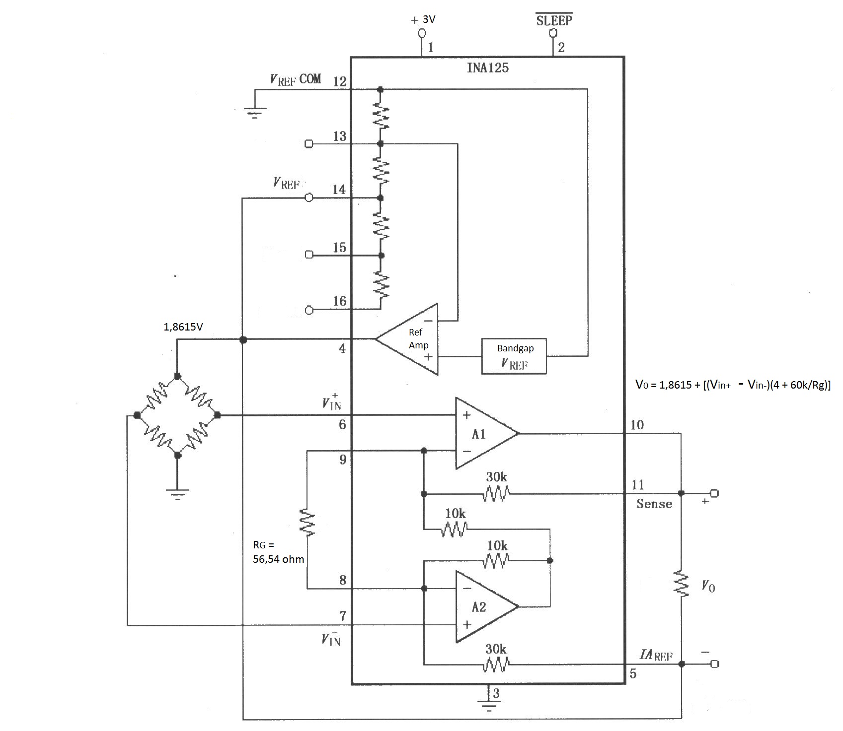
I have a strain gauge application and I use instrumentation amplifier (INA 125)
to signal conditioning. At the output of INA I have an offset of 2 Volt.

Do you recommend a circuit for removing the offset, please?

Thanks,

Antonino

  • Hello Antonio,

    Figure 6 in the data sheet is similar to your configuration.  In Figure 6, the output of the reference buffer (pin 4) drives the IA_ref pin.  This adds the reference voltage to the output of the INA125.

    If you do not want this voltage present at the output, do not drive the IA_ref pin with the reference voltage.  Such a configuration is depicted on the front page of the data sheet. 

    More importantly, however, is to note that with a 3V supply only VrefBG (1.24V) is available as the reference voltage.  Since you require 1.8615V, this device and configuration will not work.  Also, the INA125 does not have an option that provides 1.8615V.  The options are 10V, 5V, 2.5V, or 1.24V.

    Therefore I recommend looking for a discrete solution.  Perhaps you could use an adjustable LDO to generate your reference voltage.  Alternately you could use a voltage divider with op amp buffer.  You can then use a variety of instrumentation amplifiers (e.g. INA333, INA326) to amplify the differential signal.  If you select the INA333, please be sure to understand  that the output voltage range depends on the input common-mode voltage (please refer to figures 21 and 23 in the INA333 data sheet).

    I hope this helps.

  • Thanks,

    Your councils have been very helpful. The application works correctly.

    My application is the conditioning and the processing of the output signal from a strain gauge bridge of a load cell.

    I would like to get at the output of the INA125, when the bridge is balanced, an average voltage equal to half the supply voltage, in such a way as to exploit the whole dynamic of the next stage which is to be an A/D converter preceded by one or more filters.

    Now, to obtain the desired output I have used the following configuration, and I got what I wanted with Vout between 0.5 V and 2.5 V approximately.

    The problem is that I have three different output signals from the load cell. I would like to find a component capable of conditioning all three signals together but I have not found an instrumentation amplifier with four channels.

    Do you have any solution?

    Thanks a lot for the help you have given me.

    Best Regards,

    Antonino


  • Hello Antonino,

    Can you please share the data sheet of your load cell?  I don't understand why a 4-channel instrumentation amplifier is required.

    I found a document that may be of help:

    http://www.ti.com/lit/ml/slyp163/slyp163.pdf

  • Hi,

    thanks for the document.

    I would like three or four channels instrumentation amplifier becouse on the load cell I have three strain gauge bridges.

    Now I'm looking for an integrated solution that includes one pre-amp, an A/D converter and possibly a filtering stages.

    At the moment I find the ADS1234, ADS1148 and the SN65LVCP1414, but I'm not sure they are the correct solution.

    What do you recommend between the three?
    Do you have any advice for me?

    Thanks a lot,

    Antonino Proto

  • Hello Antonio,

    Thanks for the clarification.

    I recommend evaluating the ADS1234 because it is designed for use with strain gauges.  I will move this post to the data converters forum because they may have additional devices to recommend.