This thread has been locked.

If you have a related question, please click the "Ask a related question" button in the top right corner. The newly created question will be automatically linked to this question.

ADS6445EVM - BOM/Schematic mismatch

Other Parts Discussed in Thread: ADS6445

I am trying to connect an 80MHz LVCMOS clock to the ADS6445EVM board at the converter's CLKIN input (J12).

The EVM user manual (SLAU196, April 2007) says in section 2.2.4:

Users should connect a filtered, low-phase-noise clock input to J12. A transformer, T5, provides the
conversion from a single-ended clock signal into a differential clock signal. When selecting the clock signal
level, users should account for the transformer having an impedance ratio of 4, with a voltage step-up
of 2.

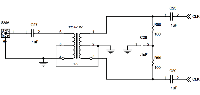
In the schematic, T5 is drawn as a center-tapped primary, center-tapped secondary with part number TC4-1W. The BOM calls out ALL transformers (T1 through T9) as a CoilCraft WBC1-1TLB. CoilCraft's website shows that the ONLY center-tapped primary, center-tapped secondary in that family is a WBC4-4L.

As you can expect, this causes considerable confusion. The physical transformer on the board is a 5 pin device with no clear markings. The colour of the phasing dot is brown, which according to CoilCraft's website means that it is a WBC1-1TL, which is a 1:1 transformer (i.e. the BOM is right, but section 2.2.4 of the EVM manual and the schematic is wrong)... 

Which is the actual part number used on this board? It's a PCB REV A board.

If I want to connect a 3.3V LVCMOS-output clock to J12 what would the recommended values for a resistor divider be (if needed?) in order to supply an 80MHz clock to this input with a minimum of fuss? I know the ADS6445 can take an LVCMOS clock directly to its pins but I would prefer not to hack up the board.

  • Hi,

    The bill of materials is the controlling document for what is installed onthe EVM.  It is the coilcraft WBC1-1TLB.

    There is no single choice of transformer or balun that we could put on an EVM that would satisfy every possible cusotmer, so we try to make the board layout flexible enough to accept a wide range of magentic devices that could be installed.  We pick a default choice to put in the BOM that will satisfy the most applications and the boards are fab'ed, tested and stocked with that choice.  But then later when someone needs to have a lower bandwidth, or higher, or wider, or wants to use a 4:1 ratio to get some gain - the board layout is hopefully flexible enough to accept different transformers from different vendors.  We sometimes even use a layout with two sets of different sized solder pads on the same EVM, (the smaller set contained withing the dimensions of the larger set) to accomodate different sized packages.  So - this EVM has a 6-pad footprint even though the default choice of transformer for this EVM did not have a center tap on the primary.  If you *did* choose such a transformer, it could be assembled onto this EVM.  Or if you chose a different turns ratio then the termination resistor values could be changed.  Or if you chose a balun instead of a transformer then the AC coupling cap is already onthe board to maintain AC coupling of the signal.  Just aiming for flexibility.

    Anyway, that is why the 'footprint' column in the BOM lists something other than the WBC1-1TLB.  It is a more inclusive footprint than just the 5-pad footprint that the WBC1-1TLB would require.

    I dont think you would need to cut down the amplitude of the LVCMOS sourced clock signal coming into the EVM.  If anything, I suspect the 50 ohm load of the cabling and termination into the EVM would drag down the amplitude of the swing from your clock souce if the clock driver is not made to drive a 50 ohm load.  If it is, then I dont think this single ended signal into  J12 of the EVM would present a problem at all.

    Regards,

    Richard P.

  • Wow, thank you for such a detailed and thorough answer!

    The specific oscillator I am using is a Connor-Winfield TVB524-080.0M; it has reasonably good specs but as you suspected, it is not intended to drive 50 ohm loads. I was going to add some series resistance to try and match the cabling and primary impedance of the transformer on the EVM. Do you have any specific recommendations there?

    The specific transformer seems to have 75 ohm DC resistance on both primary and secondary, but I see on the schematic that the secondary of the transformer is terminating differentially to 50 ohms. The cabling is also going to be 50 ohms as you suspected.

  • Hi,

    Usually a series termination at the source is used to swallow up reflections if the transmission line is not terminated at the end or is not well terminated. I think it would also make the effective load the driver sees be higher impedance, as the driver would see the source termination in series with the load of the transmission line.  So if the coax were 50 ohms and you had a series 50 ohm resistor, then the driver only is trying to drive a 100 ohm load.  But then you also get a voltage divider so you lose half your swing in the series termination.  But without it, you would suffer a reduced swing anyway if the driver can't well drive a 50 oh load.  I don't think the source termination would hurt at all.

    The Coilcraft transformers are 1:1 impedance ratio, so for a single 50 ohm coax signal source the proper termination after the transformers would still be 50 ohm differential.    Usually this would be a 25 ohm plus a 25 ohm to a center point that has an AC cap to ground, but i think this EVM spread that termination out a bit.  100 ohm differential after the transformers in parallel with a 100 ohm differenital between the transformers (if I remember right).   I don't know that spreading out the termination like this really did anything or not.  Normally we would just make R47 and R50 be uninstalled and make R48 and R49 = 25 ohms.  Different people were doing the EVMs back then.

    Regards,

    Richard P.

  • Your recollection of the clock input is correct: 

    (The actual ADC channel inputs have two back-to-back transformers to achieve better frequency response, but the clock input is the single transformer schematic above.)

    T5 is a Coilcraft WBC1-1TLB, which has a 75 ohm primary and secondary DC resistance. My reflected impedance math is a little hazy, but does this present any significant mismatch to a source expecting a 50 ohm load?  (I do realize that my particular source is expecting an LVCMOS load, I'm asking purely out of curiosity and to help anyone else who may read this in the future).

    Things are starting to come back to me, I think... The secondary is terminated to 200 ohms. This termination is in parallel with the transformer's DC resistance of 75 ohms. This would make the effective secondary termination impedance an equivalent value of 200 ohms in parallel with 75 ohms, or roughly 54 ohms, would it not? Since the transformer has a 1:1 turns ratio, this secondary impedance would be reflected back in the primary and would present the clock source driving this input with a 50 (54) ohm load?

    Thanks,

    Andrew

  • Hi,

    The DC resistance of the primary and secondary should be near zero, as they are copper windings of only a few turns.  The impedance ratio of the transformers on the analog inputs are 1:1 while the impedance ratio of the transformer on the clock input that you copied is 1:4.

    An impedance ratio of 1:1 means that if the termination after the seconday is 50 ohms differential, then the impedance looking into the primary will be 50 ohms as well.  Since the normal usage of the board is with a 50 ohm coax into the EVM, and the magnetics for the analog path were chosen to be 1:1, then the proper termination for the analog path should be 50 ohms differential.  And it is, but in an unusual fashion for this EVM.   After the magnetics we actually had 100 ohms differential in parallel with another 100 ohms between the transformers.

    The clock input uses a 1:4 impedance ratio transformer.  Again the input signal is from a 50 ohm coax.  So the proper termination after the transformer should be 4x the input or 200 ohms differential.  With a 200 ohm impedance after the transfomer, this presents a 50 ohm load looking into the transformer because of the 1:4 impedance ratio, and the input signal is properly terminated.   Note that impedance ratio is not voltage ratio.  A 1:4 impedance ratio means that the voltage swing at the secondary is twice that of the input, while the current through the secondary is half that of the primary, because we cannot get a power gain through a passive element.   Twice the voltage and half the current means 4x the impedance.   A 1:4 ratio transformer is an easy way to get some voltage gain into the ADC.

    Regards,

    Richard P.

  • Good evening, Richard,

    The transformer listed on the schematic and the transformer actually populated are not the same thing; the transformer that is actually populated for the clock input is the same 1:1 impedance ratio transformer that is populated for ALL transformers on the board (WBC1-1TLB, indicated by the brown colored index dot). This was the original source of confusion for this thread (the schematic indicating one thing, but the BOM and actual board indicating something else).

    Thank you for the correction about the DC resistance; a more careful study of the Coilcraft website shows that this measurement is listed in mOhms, not Ohms. That was a rather embarrassing oversight on my part.

    By your description, R55/R59 being 100 ohms each is designed to be used with a 1:4 transformer in order to provide a match for the 50 ohm source. If T5 on my board is a 1:1 transformer I should verify that R55/R59 are 25 ohms in order to provide a similar match.

  • Hi,

    Ah, yes - looking at the BOM spreadsheet again it looks like the clock transformer was made the 1:1 Coilcraft while the resistors R55/R59 were left at 100 ohms.   For proper matching, the BOM should either go to the 1:4 ratio transformer for T5 or change the termination resistors R55/R59 to 25 ohms.  That seems to have been missed.

    Regards,

    Richard P.

  • Excellent, thank you for sticking through with me to the conclusion. I'll verify R55/R59 and make any necessary changes.