A related question is a question created from another question. When the related question is created, it will be automatically linked to the original question.
If you have a related question, please click the "Ask a related question" button in the top right corner. The newly created question will be automatically linked to this question.
It appears everything is working if I put the DAC7811 in the standalone mode immediately after power up. If I don't send the command to disable daisy chamin mode, the DAC will only accept the first command. After the first command, it will ignore subsequent commands until I cycle power to the DAC.
I am using the DAC7811 EVM evaluation board with an IAR STM32F407 development board. The SPI signals are connected by jumper wires and are noisy.
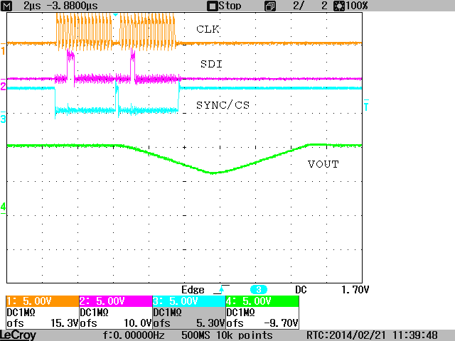
This is the scope capture, the top trace is SDIN, middle trace is the SYNC, and bottom trace is SCLK. I sent 0x1400 to set the output to +5V on the first command. The second command was 0x1c00 to set output to -5V. In the default daisy chain mode, the output voltage stays at +5V. If I first send the command ox9000 to disable the daisy chain mode, the output switches from +5V to -5V as expected.
Please see the following link for the schematic of the IAR development board. I am using SPI3 on pins 111, 112, and 113. There are pullup resistors to 3.3V on the SCLK line. SPI3_MOSI pin 113 drive the SDIN while SPI3_SCK pin 111 drives the SCLK of the DAC7811. The SYNC signals comes from an I/O Port pin 58 under software control. The SPI interface is programmed for high-level idle state and data samples on first falling edge.
I noticed on your scope capture you have 17 clock pulses while the STM32 SPI interface has 16 clock pulses but it met all the DAC7811 timing requirements. What is your clock frequency?
I made a mistake on that plot. This the correct one.
The CLK frequency is aprox. 18.3kHz. From your plot I assume that your capture is using a CLK frequency aprox. 5MHz. I took a plot at that frequency as well. Just be aware that the DAC output needs time to transition at large steps. Take a look at the plot below.
How are you injecting the signals to the Evaluation Board? A description of which pins you are using or a picture of your setup will suffice.
I think I found the problem. it appears the DAC7811 is sensitive to signal overshoost and undershoost because of the jumper wires from the the micro to the DAC7811 evaluation board. I have added 200 ohm serial termination resistors to the SCLK and SDIN signals and the DAC is now working properly.
Overshoot and undershoots on SCLK can create false edges that may cause the device to misinterpret commands. This would not have been my first guess to debugging the problem, but I really appreciate you closing the loop and letting us know how you solved the issue.