This thread has been locked.

If you have a related question, please click the "Ask a related question" button in the top right corner. The newly created question will be automatically linked to this question.

ADS1247 Output

Other Parts Discussed in Thread: ADS1247, ADS1220

Hi,

I am using ADS1247 to measure 2 x PT100 in 3-Wire Configuration. My ADS1247 configuration is,

  • No Burn Out sources active, DVDD = AVDD = 5V,
  • Internal Oscillator On, Internal Reference On, REF0 pins as ADC Reference, ADC Mode normal
  • PGA=64, Speed=10 SPS
  • DRDY/DOUT as DOUT only, IDAC = 100uA
  • IDAC sourced to A0+/A1- & A2+/A3- pairs after each conversion
  • No GPIO used
  • R_BIAS=10k, R_COMP=110E, as I my range is 50-500 deg C.

I am able to set/read-back all registers correctly. I also checked the voltage across R_BIAS which is correct for 200uA(10k x 2 x 100uA).

But my problem lies the result.  

  • I am able to read back the conversion result for each differential pair, but their is +ve offset in result. For up to 70-80 C deg, there is nearly +20 deg offset and up to 120 C deg there is nearly 10 deg offset.
  • IFC=0x000000 & FSC=0x401880 @ PGA=64
  • This offset changes to different values, when I change the PGA.
  • I have not yet done any external calibration, but tried ADS1247's SELFOCAL command without any effect.
  • One thing to note that ADC conversion results(& PT100 resistance calculation from it) as read by micro-controller matches the temperature calculated. But comparing with my another third-party PT100 temperature probe, there is offset.
  • Whatever the actual temperature & offset, result is stable around 0.5-1 C deg. 

Image below shows my circuit. Note that R_COMP=110E is 25ppm, 1% and R_BIAS=10k is 100ppm, 1%. I will go for lower ppm R_BIAS once this offset issue is resolved.

What may be the problem ?

Thanks,

Saumitra A Deshpande


  • Hi Saumitra,

    Using the RCOMP resistor can be problematic with respect to offset.  I haven't calculated but a 1% resistor will add error in the measurement.  Also any mismatch in the current sources will add additional error through the RCOMP resistor.  You can swap the current sources back and forth and average the measurement to lower any offset.

    You should always issue the SELFOCAL command at startup once you have configured the ADS1247.  This will remove the offset of the conversion process from the PGA through the modulator.

    One additional note, we have had customers with issues when using a ferrite between the AVDD and DVDD supplies.  I would suggest that the ferrite be replaced with a 10 to 20 ohm resistor if you want some additional filtering.  The inductance of the ferrite can actually choke current needed for startup where short duration high current demands occur.

    Best regards,

    Bob B

  • Hello Bob,

    Thanks for the reply.

    • I am issuing SELFOCAL at startup, but it has no effect on offset I am getting.
    • Since my desired range is 10-500 deg C, I can make R_COMP=0, will that have the desired effect ?
    • By swapping the current sources you mean, converting same pair of channels but with alternate current source and then averaging the result ?
    • I'll try replacing the ferrite with resistor. Does it need to be high precision/low ppm ?

    Thanks.

    Saumitra A Deshpande

  • Hi Saumitra,

    See my responses below in red.  Remember that you still need to calibrate your system, as there are no ideal devices.  The ratio of the RTD to the reference resistor is based on knowing precisely what the reference resistor is for the calculation.  As this has some margin of error (tolerance), as does the accuracy of the RTD itself, your system will require calibration for a highly precise/accurate system.

    Best regards,

    Bob B

    Saumitra Deshpande said:

    Hello Bob,

    Thanks for the reply.

    • I am issuing SELFOCAL at startup, but it has no effect on offset I am getting.  BB> This may not be a huge error, but it will always add to total error and can be easily removed.  All delta-sigma ADCs have some inherent offset.
    • Since my desired range is 10-500 deg C, I can make R_COMP=0, will that have the desired effect ?  BB> Making R_COMP 0 will remove the error caused by the resistor.  1% of 110 ohms is 1.1 ohms, which can result in up to a couple of degrees error without calibration.  I would remove this resistance.  The use of this resistor is much better in theory than in actual practice.
    • By swapping the current sources you mean, converting same pair of channels but with alternate current source and then averaging the result ?  BB> Yes, that is what I mean, but the need to do this is dramtically lessened if you remove or make R_COMP 0 ohms.
    • I'll try replacing the ferrite with resistor. Does it need to be high precision/low ppm ?  BB> This resistor does not need to be a precision resistor.

    Thanks.

    Saumitra A Deshpande

  • Hello Bob,

    I tried all the things you've suggested, but I am unable to remove this 20 deg C offset.Is there anything wrong with my circuit or the way I am connecting PT100 or is it a software issue ?

    Formula I currently using for resistance calculation is,

    R_PT100 = R_COMP + ((LSB/I_EXC) x ADC) where, LSB = (Vref/PGA)/(2^23-1) & Vref =  (2 x I_EXC x R_BIAS)

    This reduced to-> R_PT100 = R_COMP + ((2 x R_BIAS x ADC) / (PGA x (2^23-1))

    Further reduced to-> R_PT100 = ((2 x R_BIAS x ADC) / (PGA x (2^23-1)), where R_COMP = 0

    I think only source of error here is tolerance of R_BIAS value. I guess I will have to do the external calibration. How do you suggest to calibrate out this R_BIAS error ?

    Thanks,

    Saumitra A Deshpande

  • Hi Saumitra,

    It is most likely the assumption that the RBIAS resistor is the exact value you are using in your calculation.  You could measure this value with a precision meter using a 4-wire method (Kelvin connection), or you can calibrate out the difference.

    Calibration can be done a number of ways, and one of them is using a couple of very precise resistors instead of the RTD to determine the offset and gain slope of the system.  These types are resistors are very temperature stable with around 0.01% tolerance.  You can also buy RTD calibrator boxes made up of selectable values.

    Best regards,

    Bob B

  • Hello Bob,

    I am stuck with external calibration. I am currently using method as described in Analog Device's AN709(www.analog.com/static/imported-files/application_notes/AN-0970.pdf‎) to calibrate & remove the offset from readings. I am using high precision fixed resistors for the process.

    Whichever 2 points I calibrate as per this method, they get calibrated well, but in-between and outside these points I again get offsets from actual resistance values. As I move away from the calibration points, this offset increases---in some ranges it is+ve and in others it is -ve. Please note that this offset appears in calculated RTD resistance itself.

    Can you some throw some light on this issue ? Do I need to do multi-point calibration, 0-50, 51-100, 101-150 etc. ? My range is 10-500 deg C, that will be too much calibration data..

    Any other method to calibrate ?

    Regards,

    Saumitra A Deshpande


  • Hi Saumitra,

    There really are two considerations.  One is the calibration of the ADC for offset and gain, and the other is linearization.  If you are using complicated math, then the degree of error in the calculation itself may be an additional issue if the micro being used has limited floating point capability.  Without know how you actually implemented the calibration it is difficult to say why you are seeing errors.

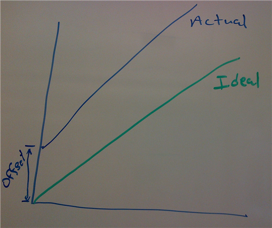
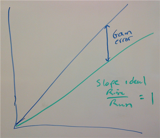
    Let's consider what the 2 point calibration actually accomplishes.  The ideal transfer function will relate to any given input resulting in a specific output.  This would be a linear response, and an equation of a line y = mx +b, where m is the gain slope and b is the offset.  In the ideal case the slope is 1 and the offset is 0.  In the real world nothing is ideal, so there will be some offset and gain error.  This is what you need to correct.

    Noise can also be a factor in this measurement, so the calibration should not be a single measurement, but rather an average of several measurements.  If you take two measurements that are close together (100 ohms to 150 ohms) for example, you may not see enough of a difference to accurately calculate the gain slope.  In the end, you need to determine the gain slope and the offset to determine the result by applying those factors to the equation of a line formula.  If you only see the correct values for the resistances you used, then I would suspect the method of correction you are using.  Most likely you are not correctly implementing the correction factors in your equation.

    Best regards,

    Bob B

  • Hello Bob,

    Thanks for the explanation. Here is what I am doing as 2-point calibration,

    1. Connect the High Precision Reference resistor in place of PT100. Measure the resistance & Temperature using ADS1247(ADCrtd, Rrtd & Trtd). Enter "actual" known value of Resistance(RCal, ADCcal & Tcal).
    2. Slope = (Rcal - Rpcal) / (ADCrtd - ADCpcal), For 1st Calibration Point, Rpcal = 0 & ADCpcal = 0.
    3. Offset = Rcal - (ADCrtd x Slope)
    4. Save Rpcal = Rcal & ADCpcal = ADCcal for next calibration point.
    5. Repeat steps 1-3 for 2nd calibration point.

    Applying the correction to measurements,

    1. Measure PT100 resistance using ADS1247.
    2. Corrected Resistance = (Measured Resistance * Slope) + Offset

    I am using AVR(ATmega128A) and all the calculations are float(F32).

    Thanks,

    Saumitra A Deshpande

  • Hi Saumitra,

    I think your problem is in how you are determining and using the slope.  I think it would be best if you looked through this document:

    http://www.ti.com/tool/TIDA-00095 

    This TI Designs is a temperature transmitter design using the ADS1220.  You should get even better results using the ADS1247.  We also have a TI Precision Design for 3-wire RTDs using the ADS1247, but it is not quite as comprehensive with respect to how the calculations and calibration is accomplished.  With the ADS1247, the offset correction can be done using the SELFOCAL command following device configuration at startup.  So what you really need to focus on is gain error of the ADS1247 and how that corresponds to the result. 

    In your calculations it is initially assumed that the current and resistor is ideal.  In the ideal case, the outcome of the transfer function is 1/2 of the reference current flows through the RTD.  By removing the current from the equation (IDAC current in numerator and 2* IDAC current in the denominator) you simply have the ratio of the resistances.  The ability to evaluate your system will be based on the precision of the measurement of your calibration resistors.  If you read through the document mentioned above, you will notice that very precise external measurements are used in determing the value of resistances used.  Here is a similar table in a different form from another data set:


    The Gain Calibration Calculation is the (Measured Resistor (value) * PGA GAIN * (2^24 -1)) / (2 * 2 * Reference Resistor (value)) in codes.  The slope is then the ratio of the codes determined in the above equation divided by the codes returned from the ADC.  In other words, the theoretical divided by the real.  In this table there was also offset correction, but this is not necessary for the ADS1247 as the offset is taken care of internally by the ADC.

    You will notice that only one resistor value was used for gain calibration.  Remember that this was really a two point calibration where the first point is 0.  This simplifies the slope equation calculation.  Is this the only way to calibrate the system?  No, there are a number of ways and this is just one of them.  If you want to use a different method that is fine but make sure that the calculations make sense for the end result.

    Best regards,

    Bob B