This thread has been locked.

If you have a related question, please click the "Ask a related question" button in the top right corner. The newly created question will be automatically linked to this question.

DXP Waveform Writer Crashing

Other Parts Discussed in Thread: DXP, DAC8811, DAC8814

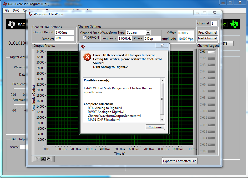
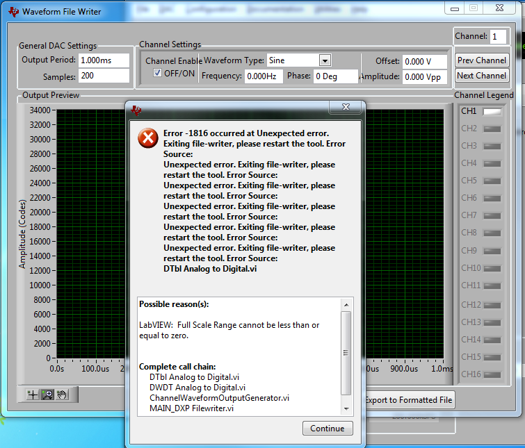
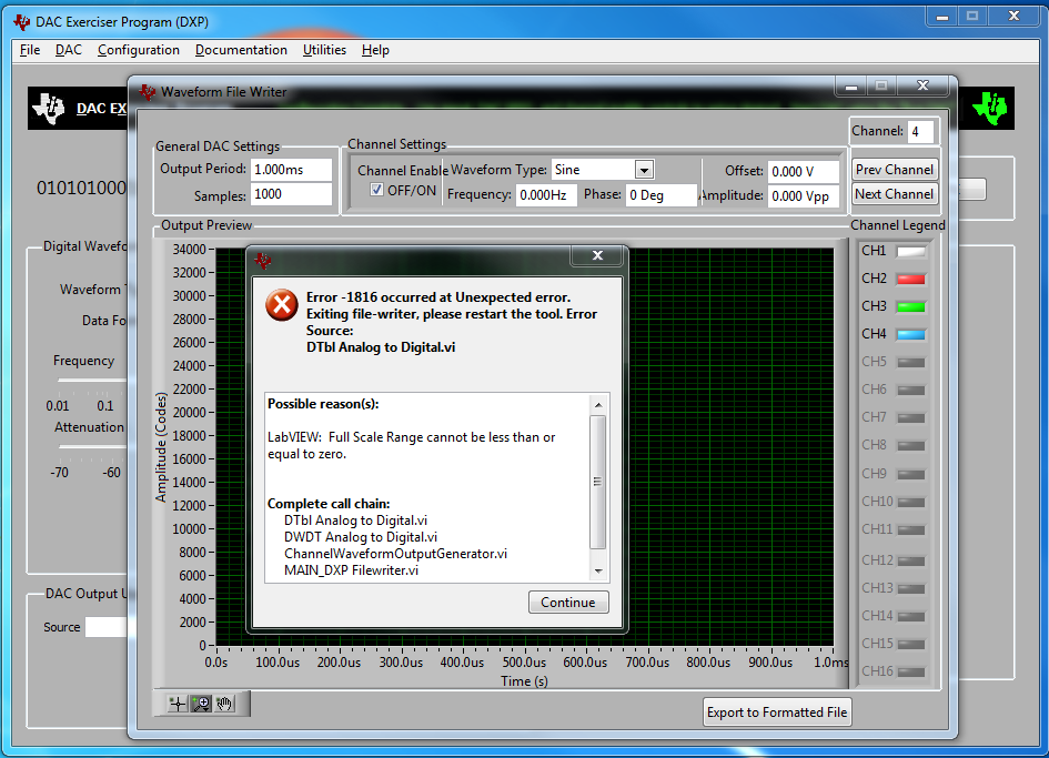
I'm trying to use the DXP DAC Exerciser Program with the Waveform File Writer, but am experiencing crashes. I've tried  under win7 and XP, with the same result.

Any suggestions? Update available? Is there a standalone version of the waveform writer? I noticed in the documentation that there must have been an older version as page 15 of SBAU146A, rev. Oct. 2012 shows a different title "Waveform File Creation Utility".

Thanks,

Carson

  • Carson,

    Can you describe what you're doing when you see this error? I'd like to try to replicate it on my end...

  • I've tried 2 different approaches. First time I simply clicked on the Channel Enable Off/On check box, and it immediately crashes. Next, I tried entering some valid numbers (as shown in the first posted screenshot) and then click on the channel enable on/off, again crash.

    When it crashes, it is not clean. I need to kill all the related processes to exit out. If I click "continue" I'm stuck in a crash loop. See attachment. Here I didn't enter anything. I just started DXP, waited for it to load, selected DAC, then went to waveform writer, and then clicked on channel enable.

  • Is this related to having a specific DAC profile loaded? With a few example parts I've not been able to replicate the same behavior.

  • OK, some progress. Previously I used the DAC8811, now I tried with the DAC8814. The first 3 channels were OK. When I advanced (using "next" in upper RH corner) and then enabled on CH4 it crashed again. (Each time connected the appropriate EVM.)

  • Carson,

    The issue seems to be because those products are multiplying DACs. Natively, a multiplying DAC has a current output and uses a transimpedance amplifier stage to create a voltage. The voltage is opposite in polarity to the reference - that is as the code increases the output voltage decreases, or becomes more negative.

    No special case was included to accommodate for MDACs in DXP it looks like - so the program reads the XML profiles and sets the positive full-scale output to a negative value, which then creates an error in the file writer.

    For your interim needs until a fix is implemented, you can modify the polarity in the XML files and the program will function as expected, but be aware that the polarity of the DAC output may not match what you expect since it's dependent on the reference polarity, and if the output stage is in a 2-quadrant (default) or 4-quadrant (bipolar) arrangement. Of course, an inverting stage could be included as well for a reference buffer etc. that would impact the results.

    I modified both device profiles you mentioned and they are attached. 

    <?xml version="1.0" encoding="utf-8"?>
    <device>
      <name>DAC8811</name>
      <revision>1.0.0</revision>
      <date>21Aug2012</date>
      <devicesettings>
        <instructionwidth>16</instructionwidth>
        <format>sbinary</format>
        <dataword>DDDDDDDDDDDDDDDD</dataword>
        <commanddefault>0</commanddefault>
        <commandlatch>0</commandlatch>
        <maxupdaterate>200000</maxupdaterate>
        <channels>1</channels>
        <interface>
          <type>spi</type>
          <polarity>0</polarity>
          <phase>0</phase>
          <maxsclk>20000000</maxsclk>
          <framebits>16</framebits>
        </interface>
        <latchpin>
          <feature>0</feature>
          <pulsepol>0</pulsepol>
        </latchpin>
        <FSplus>0</FSplus>
        <FSminus>-2.5</FSminus>
      </devicesettings>
    </device>

    <?xml version="1.0" encoding="utf-8"?>
    <device>
      <name>DAC8814</name>
      <revision>1.0.0</revision>
      <date>21Aug2012</date>
      <devicesettings>
        <instructionwidth>16</instructionwidth>
        <format>sbinary</format>
        <dataword>XXXXXXAADDDDDDDDDDDDDDDD</dataword>
        <commanddefault>0</commanddefault>
        <commandlatch>0</commandlatch>
        <maxupdaterate>1000000</maxupdaterate>
        <channels>4</channels>
        <interface>
          <type>spi</type>
          <polarity>0</polarity>
          <phase>0</phase>
          <maxsclk>20000000</maxsclk>
          <framebits>16</framebits>
        </interface>
        <latchpin>
          <feature>0</feature>
          <pulsepol>0</pulsepol>
        </latchpin>
        <FSplus>+10</FSplus>
        <FSminus>-10</FSminus>
      </devicesettings>
      <gpiofunctions>
        <function>
          <gpio>5</gpio>
          <name>/RST</name>
          <default>1</default>
          <active>0</active>
          <labels>
            <active>In Reset</active>
            <inactive>Not Reset</inactive>
          </labels>
        </function>
      </gpiofunctions>
    </device>