This thread has been locked.

If you have a related question, please click the "Ask a related question" button in the top right corner. The newly created question will be automatically linked to this question.

ADS8638 communication issue

Other Parts Discussed in Thread: ADS8638

Hi

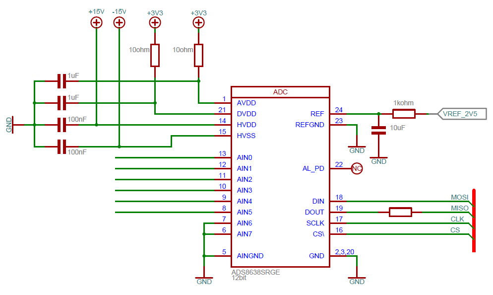
I have a custom made board with several ADS8638 on it and they are supplied like this: 
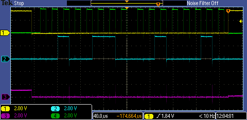
I communicate with the ADC with LabVIEW and a NI 8451 (USB SPI device) and I have attached a screenshot of the communication when I try to set ch6-7 range and then try to read ch6-7 range. My CLK runs at 50kHz

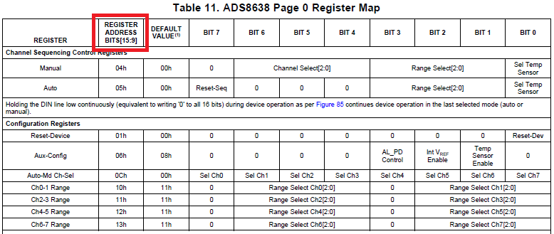
As I read the manual, to set ch6 range to +/-5V and ch7 range to +/-5V I need to send the following bits to the ADC:  

Set ch6-7 range:  00100110 00100010

read ch6-7 range:  00100111 00000000

Screenshot of setting the range:
Screenshot of reading the range:
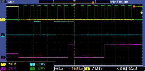
Yellow = Chip select

Green = Clock

Blue = DIN (MOSI)

Purple = DOUT (MISO)

I am clearly not reading the contents of register 13h that contain ch6-7 ranges.... I have tried to tie AL_PD to 3,3V to make sure the ADC is not in a sleep state. It makes no difference

Any thoughts on what I am doing wrong?

/Palle

  • Hello Palle,

    From the scope screenshot and bits mentioned, the command send to the ADS8638 in both SPI transactions is “read register address 09h” instead or write/read ch6-7 ranges.

    Since the first 6 bits sent are “001001”, the actual register address selected is 09h. Then, the seventh bit sent is ‘1’ for both cases meaning a read instruction. This is shown in the following image:


    Thus, SPI master is sending data shifted with an unintended ‘0’ as the MSB.

    On another note, the resistor between the 2.5V reference source and the reference pin is too large (1kohm). I don’t recommend a resistor larger than 10ohm. The reference pin needs to be driven by a low impedance source to avoid reference unsettling during fast sampling rates. I have seen these types of filtering when using noisy/low-power reference sources. If the reference is too noisy, it needs to be filtered and then buffered with an op-amp. Note than if an additional op-amp is used in between the reference source and ADC ref input, at the reference pin there should still be a 1uF to 10uF capacitor. A 10ohm can be used between the op-amp and the 10uF at the reference input pin, but make sure the op-amp has more than 50° phase margin when loaded with the resistor and capacitor.

    Regards,
    Rafael

  • Hi Rafael

    Thanks alot for the fast reply.

    As I understand the datasheet, the ADS8638 expect 7 address bits and not 6?

    And thanks for the recommendation on the Vref series resistor. 

    /Palle

  • Just following up, is it correct that the ADS8638 expect 7 address bits? (see above post)

    /Palle

  • I'm still not able to communicate with the ADC...

    Can anyone please post an example of a SPI bit pattern to send to the device with a corresponding expected reply

    any help is appreciated

    /Palle

  • If anyone else is having the same issue as me, I just wanted to share that I solved the issue... I raised the clk speed from 50kHz to 1MHz and voila, everything works like a charm. (10MHz also works fine).

    I've looked a bit at the datasheet to see if there's a minimum clk speed mentioned, but i couldn't find it.