This thread has been locked.

If you have a related question, please click the "Ask a related question" button in the top right corner. The newly created question will be automatically linked to this question.

ADS1298 with single lead ECG

Other Parts Discussed in Thread: ADS1298, ADS1291, ADS1292R, ADS1292

Hello,

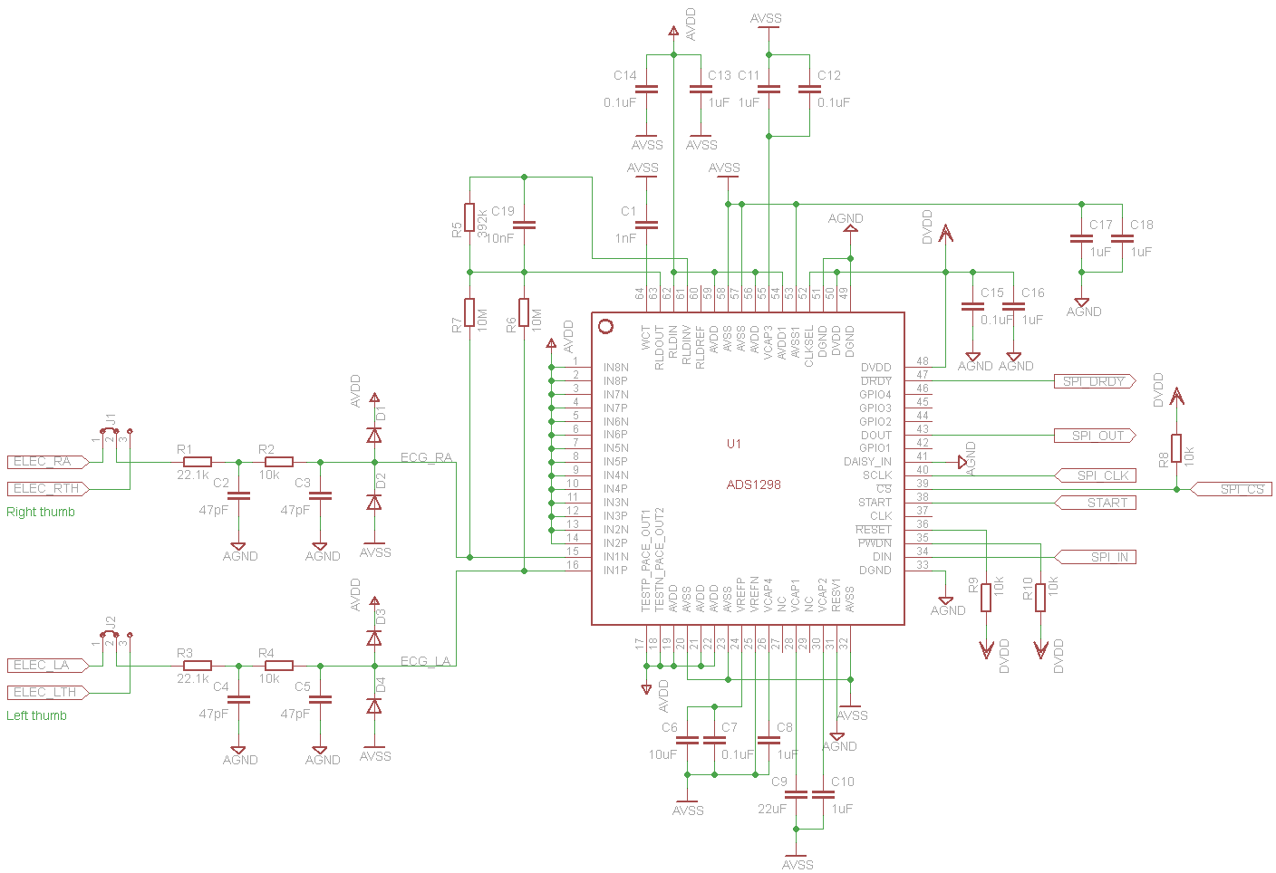
I want to create a portable ECG device and I need some opinions on the hardware design. I am using ADS1298 with single lead ECG. I want the device to offer two modes of signal detection: using electrodes which are placed on the users' arms and using electrodes placed on the PCB on which the user will place his thumbs.


I have closely followed a similar discussion (http://e2e.ti.com/support/data_converters/precision_data_converters/f/73/t/200221.aspx?pi73718=1) in order to make the connections correctly. I need your opinions on the hardware design (have I made the connections correctly? have I forgotten something?). The circuit schematic is displayed below and I have attached it to the message.

Also, I want to ask you what is the role of the R1-R2-C2-C3 group. I can see that it is a double pole RC low pass filter, but if I simulate it I obtain a cutoff frequency of aprox. 6kHz (I must mention that I took the components' values from the ADS1298ECG-F ECG Front-End Performance Demonstration Kit User's Guide). Isn't the LPF suppose to have a cutoff frequency of 150Hz? Is functioning as a low pass filter the only role of that group?


Thanks in advance,
Cristian Monea

  • Anyone? Any thoughts on the design and an explanantion for the low pass filter would be great.

  • I found out (from SBAA188 - Improving Common-Mode Rejection Using the Right-Leg Drive Amplifier) that the LPF's capacitors are 47nF, not 47pF. The simulation indicated a cutoff frequency of aprox. 70Hz (much better that 60kHz). I don't understand why TI has put 47pF capacitors in the schematic and BOM, in ADS1298ECG-F ECG Front-End Performance Demonstration Kit User's Guide.

    Any comments on my schematic, or I am alone here?

  • Hello. It worked like this the proposed design? Thanks.

  • It worked like this the proposed design? Thanks.
  • Hi! Unfortunately, I did not work because I couldn't program the ADS using SPI. I double checked the design if the power supply was correct, if the traces were routed to the correct pins and even viewed the SPI waveforms on the pins. The commands sent to the chip were correct, but it did not respond (I couldn't even read the chip ID). The design was for Analog Design contest, and I could not finish it on time. After that, my schedule got busy and I abandoned the project.

  • I understand. I would use ADS1298 for ECG measurements with only two electrodes. I would use the RA and LA electrodes without using the third electrode RL.
  • Hello Jaromír,

    Have you looked at the ADS1291? It is similar to the ADS1298 except for single lead ECG.

    Regards,
    Brian Pisani
  • Hello Brian,

    I would use a single lead ECG measurements in my school work. Can I use this connection for ADS1291? I searched the datasheet ADS1291 and I found a connection with a breathing circuit. Thanks for any reply and comment, how do I start.

  • Jaromir,

    The ADS1291 is a single channel device that comes in the same package as the 2 channel ADS1292 and the enhanced ADS1292R. For single channel ECG, you can tie the channel 2 inputs to AVDD. Then do simple ac coupling on the channel 1 input (since you are not using a RL electrode). You can also get rid of C10 for the single channel device.

    Brian

  • Dear Brian,

    I suggested circuit for measuring single channel ECG. I followed the information in the datasheets. I'm not sure with terminals connection (RLDIN / RLDREF) and (RLDINV). I followed the instructions in the datasheets and I joined to AVDD when I do not using right leg drive. You wrote me that I had to do a simple ac coupling on the channel 1 input. I have built a shematic. Do you think my shematic is ok?

    Thank you for your opinion.

    Jaromír

  • Jaromir,

    It looks like R23 and R24 are connected to 3.3V. This will exceed the input voltage range for the PGA. Also, do you have ac coupling capacitors on a different schematic page or were they intentionally excluded? You are also going to want some kind of anti-aliasing on the inputs. I recommend a cutoff frequency of ~15 kHz.

    You should tie the START pin low if you intend to control the device with the START command. Tie the PWDN/RESET pin high for similar reasons. Tie CLKSEL high to use the internal clock. The DRDY pin needs to go to the host to indicate new data are ready. I also recommend tying the GPIO pins low if unused.

    Regards,
  • I am not sure with ac coupling capacitors. I used the anti aliasing filter. For cut frequency of 15kHz. It is alright?

    thank you,

    Jaromír

  • Jaromir,

    I am referring to dc blocking capacitors that will eliminate the dc component of the signal from the body. You can look at Figure 95 of the ADS1298 datasheet for an example of this.

    The only change I would recommend for the anti-aliasing filters is that it be made into a single differential mode rc filter. By that I mean instead of C22 and C23 shunting to ground, you should connect a single capacitor between IN1P and IN1N. To get the same cutoff frequency, you will need to halve the capacitance.

    Brian
  • Thank you Brian,

    Do you think my shematic now is ok ? I looked at ADS1298 datasheet.

    1. Do you think the anti-aliasing filter is ok ? I chose C21 470pF. 
    2. Do you think the blocking capacitors is alright? Values for C23 and C22 1uF is alright? 
    3. Can I pin 29 RLDIN/RLDREF unconnected? I left him floating for now. Or I have to use a voltage reference AVDD / 2?

    Thank you inadvanced.

    Jaromír

  • Hello Jaromir,

    It looks good now! You can leave RLDIN/RLDREF floating.

    Brian
  • Hello Brian,

    I used the proposed scheme for PCB production. I want to use the ADS1292. May I ask how do I set up some registers? As you know, I want to measure single lead ECG  and I do not use for measuring third RL electrode. I prepared for this measurement the registry settings. I'm not sure the setting marked red bits. Could you please help me?

    1. I do not know how to set up a bit5 and bit3 in the CONFIG2 register. I am using the internal clock.
    2. I do not know how to set up a bit3:0 in the CH1SET register. When I use only two measuring electrodes. Do I leave the default settings 0000 or 1000 I have set up both positive and negative inputs are connected to RLDIN.
    3. Do I set a Bit7 in the CH2SET on the default? Or I have to set bit 7 registry CH2SET to 1 when I do not use this channel?
    4. I do not know how to set up a bit7:6 and bit5 in the RLD_SENS register.
    5. I do not know how to set up a bit1:0 in the GPIO register. When I have GPIO1 and GPIO2 connected to GND.

    Thank you for your answer. Jaromír

  • Jaromír,

    See my comments:

    1. Bit 5 should be set to 1. This enables the internal reference voltage for the ADC. Bit 3 depends. If you are using the internal oscillator and want to have the internal clock output to the CLK pin, set that bit. Otherwise it should be cleared. Table 9 in the datasheet shows the truth table.
    2. Use "normal electrode input".
    3. You should turn off the channel if you're not using it. By the way have you looked at the ADS1291? It is the same package and functionality as the ADS1292 but with only 1 channel. It will be a little cheaper.
    4. Bit 6, 7 defaults should be fine. Bit 5 should be set since it turns the RLD amplifier on. You are using the RLD amplifier to bias your inputs.
    5. Doesn't matter. They will be read-only as inputs so anything you write to them will be ignored.

    Regards,

    Brian

  • Thank you Brian,

    Please. Do I set a Bit1-0 in the RLD_SENS on the default? When I connected two resistors (R23, R24) to the channels IN1N and IN1P through output RLDOUT. Or I have to set bit 1-0 registry RLD_SENS to 1?

    Jaromír
  • Hello Jaromír,

    If you want them to be set, you have to set them. They are 0s by default.

    Brian

  • Hello Brian,

    I tested the write and read registers. It's alright. In the first case I tried to communicate with ADS1292 via Raspberry Pi3. In this case, I could not communicate with the ADS1292. I could not read or write to the registers. I've programmed it through c # and used the wiringPi library. Anyway, this did not work and I did not find out why.

    Then I tried another way with NUCLEO-F103RB. Here it looks promising. With c code. Registry setup is fine and reading too. Now I want to test the test 1 Hz square signal.

    I would like to ask you to set up some registers. You know that I do not want to use the third electrode to measure one lead ekg.

    That's how I want to set up registers. ADS1292.

    1. In the RLD SENS registry setting, I have to set bit1 and 0 to 1. That is alright. Right?
    2. When I have analog inputs IN2N, IN2P, IN3N and IN3P connected to AVDD, do I have to leave 0 in the CH2SET register? Or should I set bit 7 to 1 and set bits (3:0) to 0001 = Input shorted (for offset measurements)?

    Thank you so much. 

    Jaromír

  • Jaromir,

    1. You should clear those bits to make the RLD amp act like a simple buffer.
    2. You can clear bit 7 of the CH2SET register. This will disable the channel. By the way, have you looked at the ADS1291? It is a 1 channel version of the ADS1292 with the same PCB footprint. It will probably be cheaper than the ADS1292.

    Regards,

    Brian