This thread has been locked.

If you have a related question, please click the "Ask a related question" button in the top right corner. The newly created question will be automatically linked to this question.

Single lead ECG device

Other Parts Discussed in Thread: ADS1298

Hello,

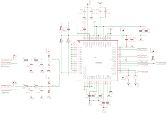
I want to create a portable ECG device and I need some opinions on the hardware design. I am using ADS1298 with single lead ECG. I want the device to offer two modes of signal detection: using electrodes which are placed on the users' arms and using electrodes placed on the PCB on which the user will place his thumbs. Maybe I can also use the RL electrode when the device is in the first mode of use.

I have closely followed a similar discussion (http://e2e.ti.com/support/data_converters/precision_data_converters/f/73/t/200221.aspx?pi73718=1) in order to make the connections correctly. I need your opinions on the hardware design (have I made the connections correctly? have I forgotten something?). The circuit schematic is displayed below and I have attached it to the message.

Also, I want to ask you what is the role of the R1-R2-C2-C3 group. I can see that it is a double pole RC low pass filter, but if I simulate it I obtain a cutoff frequency of aprox. 60kHz (I must mention that I took the components' values from the ADS1298ECG-F ECG Front-End Performance Demonstration Kit User's Guide). Isn't the LPF suppose to have a cutoff frequency of 150Hz (or 15kHz, since ADS1298 works at 30ksps)? Is functioning as a low pass filter the only role of that group?

Thanks,

Cristian Monea

  • I found out (from SBAA188 - Improving Common-Mode Rejection Using the Right-Leg Drive Amplifier) that the LPF's capacitors are 47nF, not 47pF. The simulation indicated a cutoff frequency of aprox. 70Hz (much better that 60kHz). I don't understand why TI has put 47pF capacitors in the schematic and BOM, in ADS1298ECG-F ECG Front-End Performance Demonstration Kit User's Guide.

    Any comments on my schematic, or I am alone here?

  • Hi Cristian,

    It is better to use 47pF capacitors rather 47nF capacitors for at least two reasons:

    1/ If you use 47nF and the patient electrode impedance is high (and it will be typically 50 kilohms or more if you just hold the electrodes) as it will greatly lower the bandwidth of the low pass filter to such an extent that ECG waveshape may be compromised.

    2/ In general the higher the input impedance the higher the common mode rejection (mainly mains power frequency rejection). Increasing the capacitors to 47nF reduces the input impedance and will reduce the common mode rejection.

    regards,

    Richard 

  • Hi Richard,

    Thank you for the advice. I did not think about the patient-electrode (or skin-electrode) impedance.

    I now understand why lower value capacitors are needed, but isn't the cutoff frequency too high when using 47pF? E.g., my simulations have indicated the next cutoff frequencies (using 47pF): 35kHz (input resistor of 50k - R1 in my schematic), 18kHz (input resistor of 100k) and 1.8kHz (input resistor of 1Meg). In fact, what is the purpose of the low pass filter?

    Regards,

    Cristian Monea

  • Hi Cristian,

    The input filter is mainly to remove RF frequencies and to act as an anti-aliasing filter for the sigma-delta converter in the ADS1298. The third order sync filter does a reasonable job  (see Fig 26 of data sheet) of removing most of the signals that are likely to cause aliasing but as can be seen from Fig 30 of the datasheet when the input signal is near multiples of the modulator frequency (Fclk/4 for high res. mode or Fclk/8 for low power mode) there is practically no attenuation. 

    In general I would operate the ADS1298 at a high output data rate then use a digital filter to get your desired frequency response. By running the ADS1298 at a high data rate you are less likely to get aliasing from signals between Fdr/2 and Fdr (where Fdr = output data rate) since physiologically the amplitudes of signals in the kilohertz range are much lower than signals below 500Hz.

    But there is another benefit from high data rates. From Fig 26 the sync. filter is only about 13dB down at Fdr/2. If Fdr is say 16kHz then it is mainly signals in the 8kHz to about 14kHz where the sync filter is less than 40dB down that you have to worry about as they can alias. Between 14kHz and 16kHz the sync filter has high attenuation which greatly reduces any aliasing. Now any 8kHz to 14kHz signals will alias into the 2kHz to 8kHz band where they can easily be removed by using a digital low pass filter (possibly an FIR so as not to distort the waveshape) at your desired bandwidth of say 100Hz. The filter will also reduce the noise to roughly the same value you would have achieved had you used the ADS1298 with Fdr=100.

    regards,

    Richard


  • Hi Richard,

    As I understand, it is better to operate ADS1298 at high data rate because it reduces the chance to get aliasing from higher frequency signals (because they have smaller amplitudes). However, this aliasing is unavoidable, but it is removed by using a digital filter.

    Please correct me if I did not understand the explanation correctly.

    Regards,

    Cristian Monea

  • Hi Cristian,

    Your summary is correct.

    If it was possible to access the signal after the initial amplification but before the ADC then an analogue filter at the desired signal bandwidth could be used. But this would require more hardware, particularly in multi-channel applications. Executing the filter in software is more flexible and generally lower cost.

    Regards,

    Richard