


Other Parts Discussed in Thread: ADS7953
Hello, someone, please help!
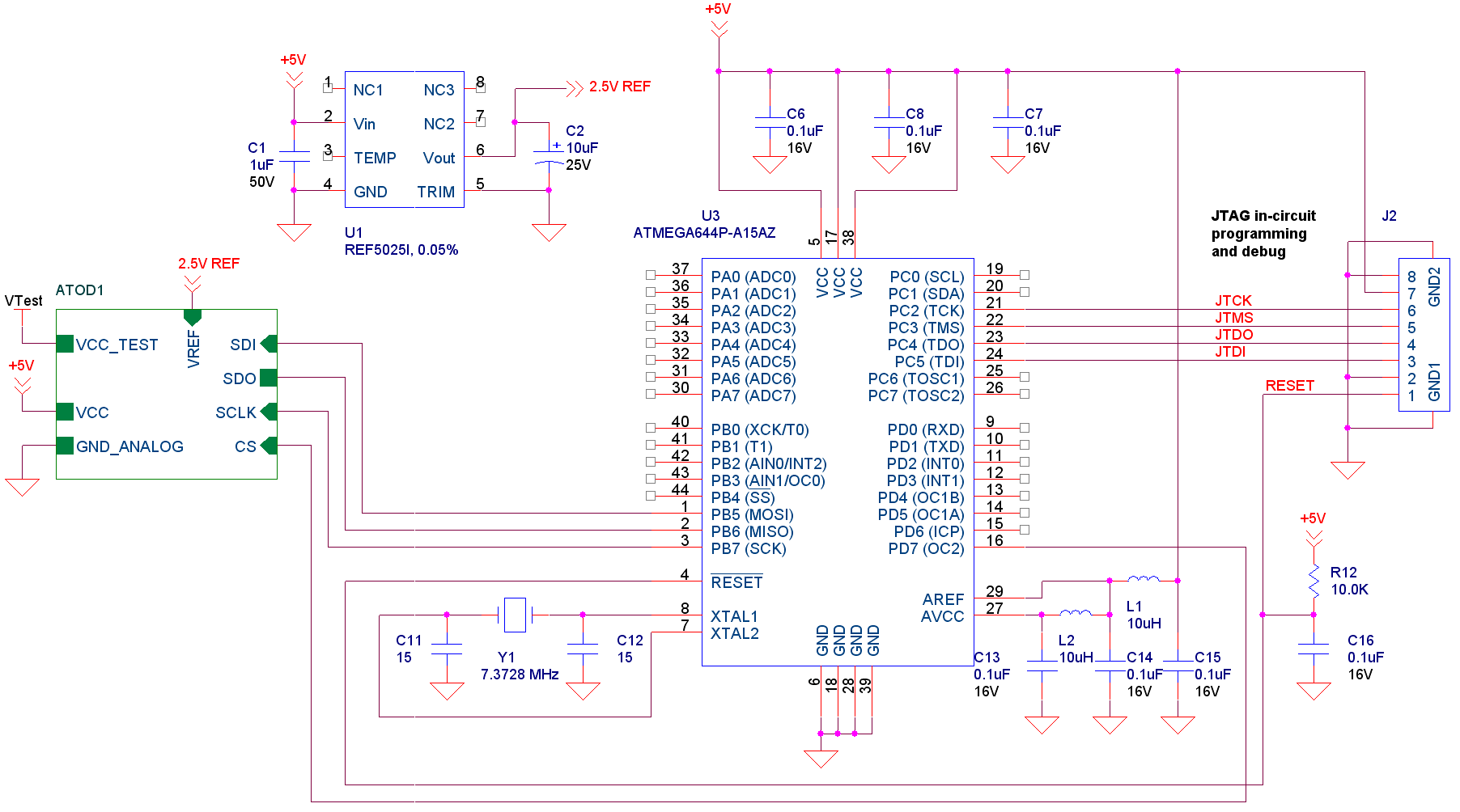
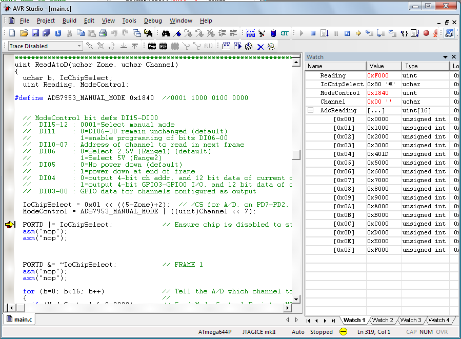
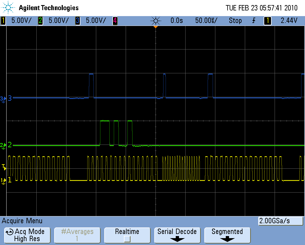
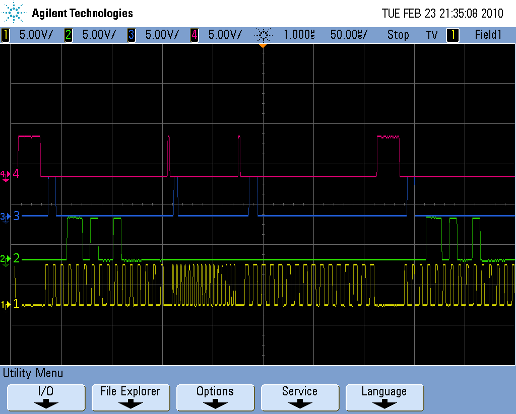
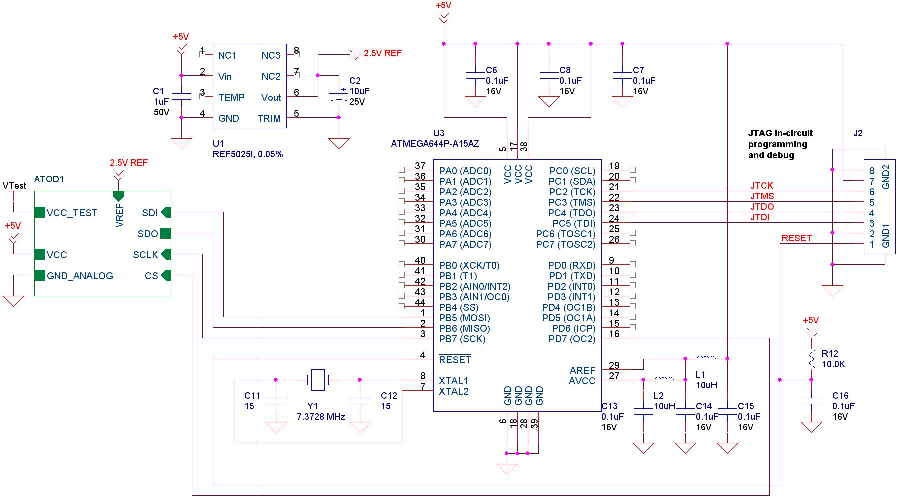
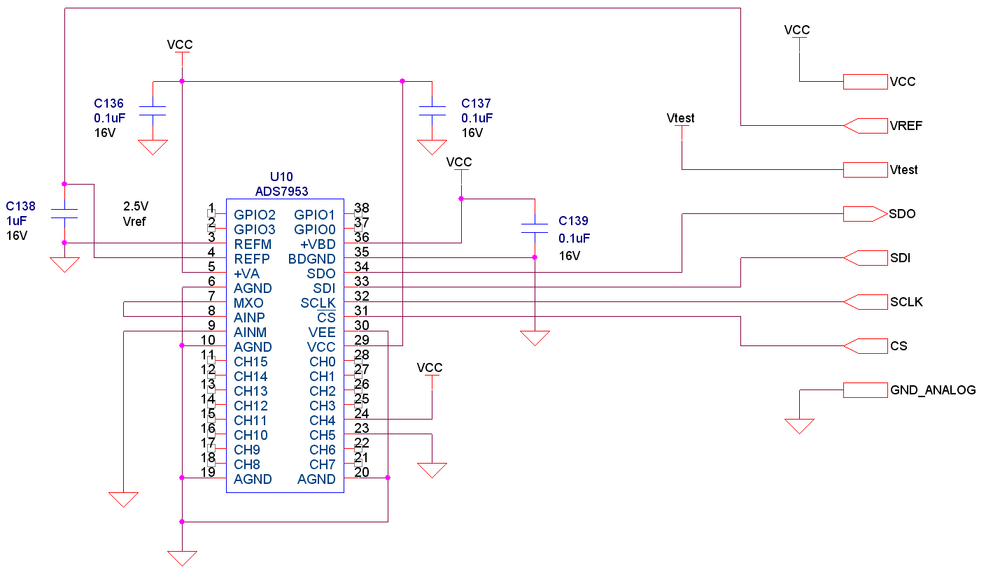
I built a small pcb with an ADS7953 and an AVR microcontroller for measuring DC voltage levels. Vcc = 5V, Vref = 2.5V, AINP is directly connected to MXO, the processor is running at 7.3728MHz. (140nS per clock). I currently have channel 4 connected to 5V, channel 5 connected to 0V, all other channels float. I am bit-banging the serial communication and posted the source code below. I'm using manual mode with Range2 and read all 16 channels in a continuous loop. In debug mode, I pause the code and use the watch window to view the current samples which are stored in an array.
When I read from channel 4, I currently see 0x401C. I would expect to read 0x4FFF for a full-scale measurement. When I read channel 5 (or any of the floating channels) I get 0x5000, 0x6000, 0x7000, etc. While these values are incorrect, I see the channel number so I think my read/write is working correctly.
When I add some 1 second delays between frames, channel 4 will only get as high as 0x402F. I never get close to 0x4FFF! Also, with delays I start to read values from the grounded and floating channels such as 0x501F, 0x6020, 0x701A, etc.
The interface seems so simple. What could I possibly be doing wrong?!
Thanks,
Gordo.
/***********************************************************************************************************************
Description: Read an A/D chip in manual mode.
The A/D can run with clk up to 20MHz (50nS), we're running at 7.3728MHz.
A single NOP is used for delay = 136nS.
Parameter: Zone = Which A/D chip (1-6) to select
Channel = Which one of 16 (0-15) channels on the A/D chip to read
Return Value: Two byte (12-bit) A/D reading.
Global Symbols:
Specialities:
***********************************************************************************************************************/
uint ReadAtoD(uchar Zone, uchar Channel)
{
uchar b, IcChipSelect;
uint Reading, ModeControl;
#define ADS7953_MANUAL_MODE 0x1840
// ModeControl bit defs DI15-DI00
// DI15-12 : 0001=Select manual mode
// DI11 : 0=DI06-00 remain unchanged (default)
// 1=enable programming of bits DI06-00
// DI10-07 : Address of channel to read in next frame
// DI06 : 0=Select 2.5V (Range1) (default)
// 1=Select 5V (Range2)
// DI05 : 0=No power down (default)
// : 1=power down at end of frame
// DI04 : 0=output 4-bit ch addr, and 12 bit data of current channel (default)
// : 1=output 4-bit GPIO3-GPIO0 I/O, and 12 bit data of current channel
// DI03-00 : GPIO data for channels configured as output
IcChipSelect = 0x01 << ((5-Zone)+2); // /CS for A/D, on PD7-PD2, PD7=Chip0, PD6=Chip1, etc.
ModeControl = ADS7953_MANUAL_MODE | ((uint)Channel << 7);
PORTD |= IcChipSelect; // Ensure chip is disabled to start
asm("nop");
asm("nop");
PORTD &= ~IcChipSelect; // FRAME 1
asm("nop");
asm("nop");
for (b=0; b<16; b++) // Tell the A/D which channel to read in first frame
{ //
if (ModeControl & 0x8000) // Send Mode Control Register MSB first
PORTB |= 0x20; // SDI pin = Hi;
else
PORTB &= 0xDF; // SDI pin = Lo;
PORTB |= 0x80; // Set clock high
asm("nop");
ModeControl <<= 1; // Load next MSb to send
PORTB &= 0x7F; // Set clock low
asm("nop");
}
PORTB &= 0xDF; // Leave SDI pin Lo
PORTD |= IcChipSelect; // Disable chip to end frame
asm("nop");
asm("nop");
PORTD &= ~IcChipSelect; // FRAME 2, channel is acquired
asm("nop");
asm("nop");
for (b=0; b<16; b++) // Read channel data
{
PORTB |= 0x80; // Set clock high
asm("nop");
PORTB &= 0x7F; // Set clock low
asm("nop");
}
PORTD |= IcChipSelect; // Disable chip to end frame
asm("nop");
asm("nop");
PORTD &= ~IcChipSelect; // FRAME 3 - channel is sampled
asm("nop");
asm("nop");
Reading = 0x0000; // Initialize reading bits to 0
for (b=0; b<16; b++) // Read channel data
{
Reading <<= 1; // Shift bit in, no effect first time through loop
PORTB |= 0x80; // Set clock high
asm("nop");
if (PINB & 0x40) // Read bit, is SDO pin Hi or low?
Reading |= 0x0001; // bit = 1
else
Reading &= 0xFFFE; // bit = 0
PORTB &= 0x7F; // Set clock low
asm("nop");
}
PORTD |= IcChipSelect; // Ensure chip disabled before leaving
return(Reading);
}


