This thread has been locked.

If you have a related question, please click the "Ask a related question" button in the top right corner. The newly created question will be automatically linked to this question.

ADS1299 EVM DIFFERENTIAL INPUTS SETUP

Other Parts Discussed in Thread: ADS1299

Hy Guys.

can anybody  guide me?, guide me too user is unclear.

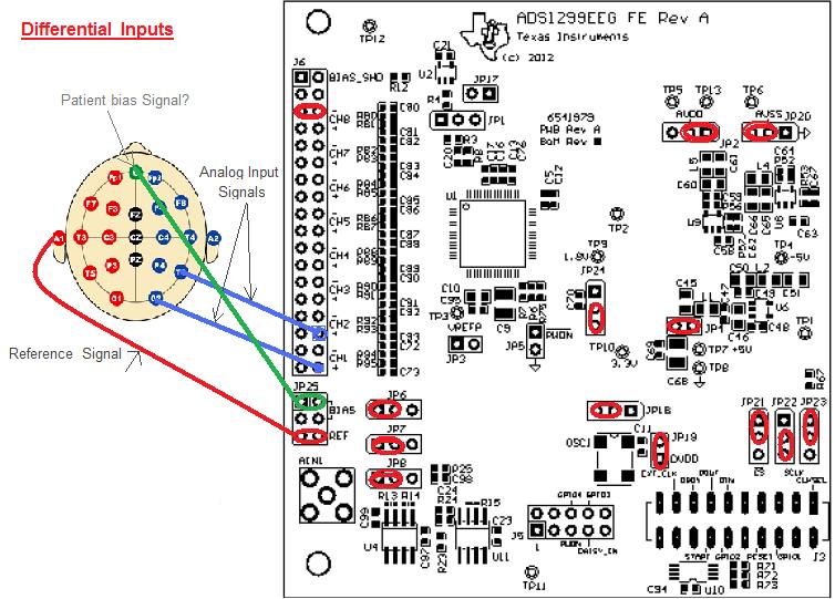
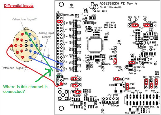
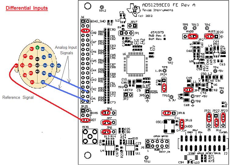
I've been trying to initialize ADS1299 EVM in DIFFERENTIAL INPUTS mode, but I dont understand why it doesnt work.

1.-INP is the positive input of the normal electrode(CH1+, CH2+), but where is connected INN (-)? Is not connected?. In software I out "normal electrodes"

2.- I think that I need to be operated with a bipolar supply, therefore JP2=1-2, JP20=2-3.

3.- As I use reference signal. Set the SRB1 bit in the MISC1 register to route the SRB1 pin to the negative in software.

4.- all of them software I used at defautl.


Norma

  • Hola Norma, 

    Thanks for the details on your setup. 

    Norma Ramirez said:
    1.-INP is the positive input of the normal electrode(CH1+, CH2+), but where is connected INN (-)? Is not connected?. In software I out "normal electrodes"

    When you set SRB1 = 1, the external INN pins are not connected to the PGA inside the ADS1299. Instead, the signal on SRB1 is routed internally to PGAN (see Figure 19 for Input Multiplexer block diagram). In your setup, you are driving SRB1 with your reference electrode, which should be fine for single-ended EEG measurements.

    Have you tried buffering your reference electrode through U4? To do this, change JP8 to [2-3].

    If you need me to look over your register settings, I will gladly do so.

    Saludos,

  • Ryan Gracias!

    Do you mind I keep SRB1 Bridge (JP25 5-6) and change JP8 (2-3)?

    and the others jumpers are ok?

    In the software ¿Do I need to make any change?

    I ve device defaults, just set SRB1 close...  do I need to change it closed again?


    Gracias por ayudarme.

    Norma

  • With JP25 [5-6] connected, BIAS_ELEC and REF_ELEC will be shorted together. Was this your intention?

    Because JP6 = [1-2], the BIAS_ELEC signal is simply a mid-supply voltage buffered by U11. This would equal 0V because you are using dual-supplies (+/- 2.5V).

    In contrast, the REF_ELEC will carry some DC bias and some local EEG AC signal (assuming you still drive the patient).

    I'm not sure which option is best for your single-ended measurements: INxN = BIAS_ELEC (mid-supply), or INxN = REF_ELEC (DC+EEG). I would experiment with removing JP25[5-6] and use REF_ELEC as your SRB1 input. Connect the reference electrode to JP25[6] only. To buffer the REF_ELEC signal and give it better drive capability, use JP7[1-2] and JP8[2-3].

    Lastly, you can always confirm your register settings using the ADC Register tab -> Register Map -> Refresh Registers.

    Saludos!

  • Hi Ryan

    In order to reduce noise, I want (tried) to do in DIFFERENTIAL INPUTS (not single ended). I followed 4.6.1, so I change the JP2(1-2), JP20(2-3),JP6 (5-6) jumpers.

    According to what I understood from the users guide (section 7) ADS1299 EVM has dedicated electrodes (BIAS_ELEC, REF_ELEC) and I can use both in the same time...  I dont understand that is through JP25 or through software.

    for your advice, I have changed the JP8 (2-3) and REF_ELEC to JP25 (6)  and remove JP6(1-2).. but to be differentially, I need ... BIAS_ELEC in order to comparate 2 active channels.

    Gracias de nuevo

    Norma


  • Hello Norma,

    about your ECG question and the register mapping you send me.

    Ba lack of time I only had a short view over your system, but for ECG the Gain of 24 is much to high and you will not see much.

    Hope this could help.

    Regards Melanie

  • It is nice to meet you. I have some questions about ADS1299. Is REF connected to CZ? Fz to GND, and CH1p to Fp1? I would appreciate to have your answers. Thanks in advance