This thread has been locked.

If you have a related question, please click the "Ask a related question" button in the top right corner. The newly created question will be automatically linked to this question.

DDC232C based design issues

Other Parts Discussed in Thread: DDC232

I have designed my data acquisition application board using DDC232C, I face 2 major issues

(1) First we face missing code problems, The same missing codes were seen in Test mode of DDC332C.

 
I tried 2 devices total and 2 boards total , missing codes on the second board is the same as the first board. Pattern is every 14th sample is missing consecutive 4 times, followed by 13th sample.
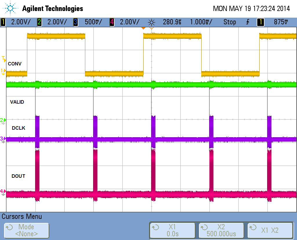
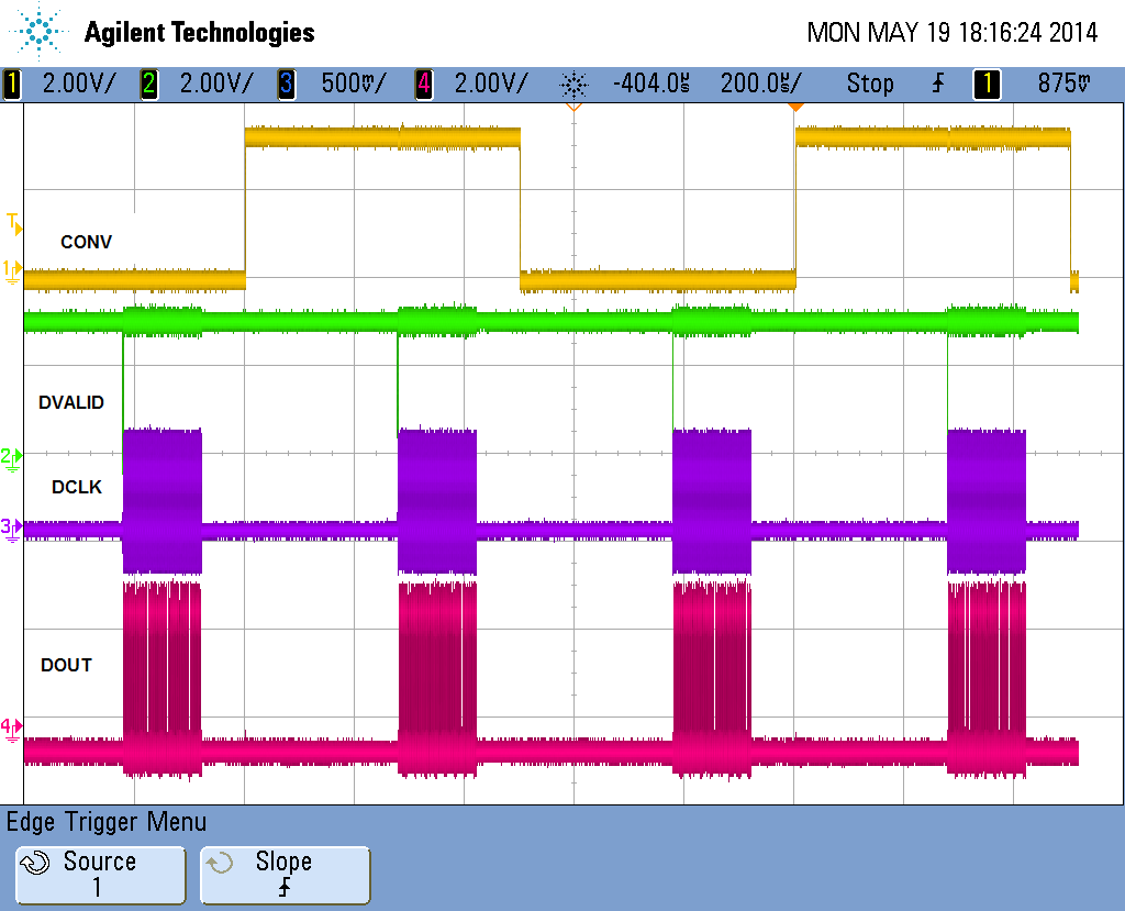
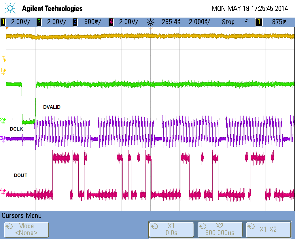
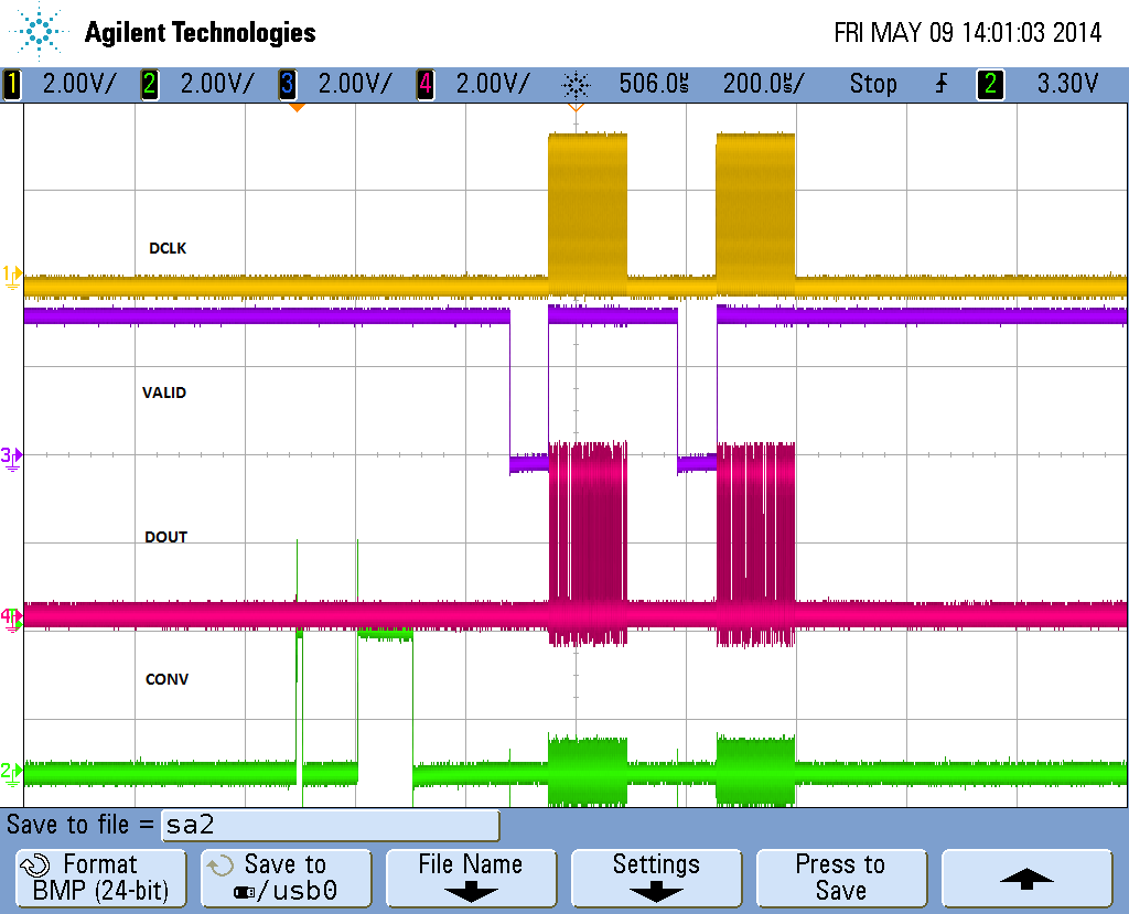
I have verified that the problem is not caused by any other area of my design by observing waveform on DSO at the o/p of DDC232 (DOUT signal with reference to DCLK). It matches with the data read and sent to PC.
 
The missing code combinations are not there when 16 bit mode is used, since they fall at intervals of 13 and 14 codes.
The design parameters of my board are as below:
CLK = 5Mhz, DCLK = 10Mhz, CONV = non continuous mode operation with side B integrated first, (with integration time: 100uS), VREF: 4.096 V,  typical range is 6 / 7, output format 20bit.
 
(2) Second issue is I found multiple peaks are built up in histogram of noise data in many cannels.
I have tried all suggestions made by you (adjusting few cycle between DVALID and DCLK) and also tried different CLK, integration times etc but the same codes are missing.  I hope to help for a solution soon. Even I tried in continuous mode operation also, behavior is same.
 
Thanks in advance
 

K.JHA

  • Kuldip,

    Thanks for contacting us. How were you able to look at all samples output by the device on the DSO? to Make a histogram you need many samples, how did you collect these if not using your FPGA or on board memory?

    Could you post a screenshot of your DDC232 signals including DCLK, DOUT, DVALID, and CONV in non-continuous mode and also in continuous mode?

    Regards,

    -Adam

  • My board design contains FPGA, and ethernet interface for data transfer. We keep on
    acquiring samples and send to PC on every event. As asked I am attaching snaps of
    CONV, DCLK, VALID, DOUT and Configuration data also. 
    I am attaching acuired spectrum , for 100uS integration time, 20 bit, Range 6, chip
    ver 0, non-cont mode
    
    let me know the issues in my design. I asserted DCLK, after providing different
    delays with DVALID, but results same.
    
    with regards,
    
    Kuldip
    
  • My board design contains FPGA, and ethernet interface for data transfer. We keep on
    acquiring samples and send to PC on every event. As asked I am attaching snaps of
    CONV, DCLK, VALID, DOUT and Configuration data also. 
    I am attaching acuired spectrum , for 100uS integration time, 20 bit, Range 6, chip
    ver 0, 
    
    let me know the issues in my design. I asserted DCLK, after providing different
    delays with DVALID, but results same.
    
    with regards,
    
    Kuldip
    
  • Kuldip,

    Thanks for your scope screenshots. I see two of them, are these two both non-continuous mode? I would like to see the same scope shots but for the continuous case. 

    Looking at your email including the two pictures from your GUI (one shows a Gaussian distribution and the other a spectrum with two peaks) could you explain the differences between each? My thought is that one is a graph of all channels all data, the other plot is of only one channel? The spectrum with 2 peaks, each peak may be one Side of that particular channel. For example, the left peak may be the A-side, right peak the B-side. We know there will be some offset between A and B side, this should be on average 100 codes in continuous mode operation according to the datasheet, since you are in Non-continuous mode this will be different. 

    Regards,

    -Adam

  • I am attaching snap shot of scope for continuous mode for 500uS and 2mS integration timing. Also I have attached the DCLK and DOUT in zoom. There is data file attached for continuous mode, I found very random data on channel 1. I am unable to understand this behavior.

    Has any one used DDC232C chip in 20 bit mode in non-continuous mode and got the desired performance as claimed in datasheet ( noise performance ).

    I have tried to insert wait state between DVALID and DCLK, that also didn't help.

    this zoomed one for DCLK and DOUT

  • Kuldip,

    Looking at your scope plots, you are running at 5MHz CLK (since DValid triggers at ~270uS and occurs at 1382 cycles of CLK after the CONV edge). Can you confirm this?

    It also looks like your DCLK is running at 5MHz. These numbers should be fine but need to be included in your posts since they differ from your original post and are highly important. Can you confirm this?

    It doesn't look like you are violating any timing parameters.

    I would not expect any surprises in non-continuous mode but please note that the spec is given under the conditions on top of the table (in this case continuous mode).

    Let's try fix continuous mode first before introducing non-continuous mode. 

    Is your CLK synced with your CONV? For best performance it should be.

    As mentioned in the datasheet, DOUT data is shifted on the falling edge of DCLK. We therefore recommend capturing the data on your FPGA on the rising edge of DCLK so that the data is stable. Where are you capturing at the moment?

    Regards,

    -Adam

  • Hi Adam,

    In my design CLK = 5MHz, DCLK = 5MHz , and CONV is synced with SCLK. I am capturing data on the rising edge of DCLK in FPGA.

    I have tried DCLK = 10Mhz also, and with few CLK cycles delay of DCLK after DVALID assertion, but didn't help in fixing problem.

    Regards,

    Kuldip

  • Kuldip,

    Could you explain SCLK? I assume you mean CLK? 

    I would delay at least 2uS after Dvalid asserts. This is not a hard rule but it might help. 

    Could you share your configuration register settings?

    Do both of the problems you originally mentioned go away when you use 16-bit mode? If this is the case you need to look at your capture solution. Are you using the same capture code for both 16 bit and 20 bit mode? I feel that if the problems go away at 16 bit mode then the part is capable of generating the missing codes but you might be capturing them slightly off in 20bit mode. 

    Regards,

    -Adam

  • Kuldip,

    Thank you for contacting us, I hope I have answered your questions.

    Please post again if we can help with something else.

    Regards,

    -Adam