This thread has been locked.

If you have a related question, please click the "Ask a related question" button in the top right corner. The newly created question will be automatically linked to this question.

AMC1200 AMPLIFICATION PROBLEM

Other Parts Discussed in Thread: AMC1200

Hi,

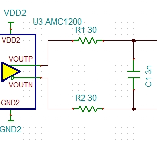
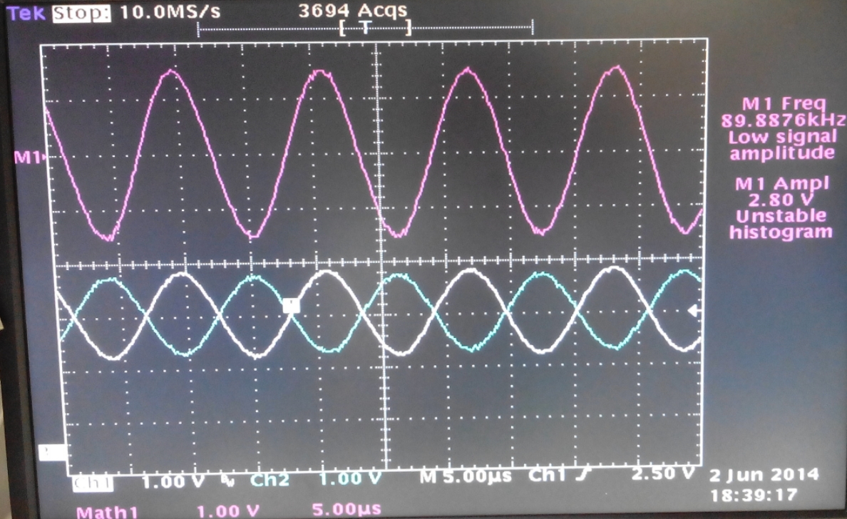
We are trying to measure the ripple in a 120 V dc source .The ripple is about 50mv P-P at 70 Khz. We are using AMC1200 for isolation. 

The response of the Isolator is gradually degrading from a gain of 8 times to about unity in 10 minutes of powering the the circuit. We are clueless on the behavior and any pointers would be highly appreciated. 

Here is the circuit,

Thanks,

Varaprasad.

  • Hi Varaprasad,

    Welcome to the e2e forum!  I've not seen or heard of any issues with the gain of the AMC1200 changing like this.  Is this issue related to a single device or multiple devices/boards?  Can you please provide details of your LPF?

  • Hi Tom,

    Thank You. We are using LTC1563 configured as a low pass ( 100 Khz) Unity gain filter. We verified the filter response with a function generator and with the actual power source. The o/p is as expected , both before and after the AMC device damage/degradation.

    The device is responding to the frequency but the o/p is unusable as it is distorted and gain is close to unity. I guess the device is damaged .We already lost one more. We are yet to understand the reason for the damage. Any inputs on the design may be helpful.


  • Hi Varaprasad,

    Can you provide screen captures of the input/output voltage?  Also, it's not clear from your schematic how LGND and uC_GND are tied on the user side.  On the high voltage side, how are PGND and HGND connected?

  • Hi Tom,

          Once I am in office tomorrow, I should be able to post the screen captures .

           On the Ground aspect,

        1) LGND and uC_GND are independent. The AMC device and the Tiva are powered from two different sources. As differential sampling is used on Tiva , we  didn't  tie the Gnds together.

        2) PGND and HGND are also separate in our current design.The previous design in which we blew another device has PGND and HGND tied together , with all the other aspects remaining the same.

  • Hi Tom,

    I guess our problem is partially solved. We modified the design and it yielded some results. Key changes

    1) Added 1 MOhm in parallel to AC coupling capacitor, before the LPF.
    2) Added filter to the AMC device Input signals.
    3) Add output filter cap across the output signals 
    We verified with two sources. Attached document has the details. We have a couple of issues
    1) The amplification is not 8x. 
    2) O/P signal has distortion.

    - Any suggestions for improving would be helpful.

    On the other aspect, do we need to bias the VINN at 2.5 volt as suggested in some of the designs used for measuring the AC Line voltage.I don't see the biasing details in the datasheet. 
  • Hi Varaprasad,

    We are not surprise to see that the gain is not 8X, since the typical bandwidth of AMC1200 is 100kHz, and you are using 90kHz in the test, and the 100kHz low pass unity gain filter will attenuate your signal too, So is that possible for you to use a lower input frequency (eg: 20kHz) source to test it?

    Are you driving the AMC1200 in full-differential way? do you know the output impedance of the LPF? would you give us more detail about how you connect the LPF to the AMC1200?

    We have not see any needs for bias the VINN to 2.5V as long as the input absolute voltage is within the range.

    Best regards,

    Martin Li

  • Hi Martin,

         It is not possible to test at lower frequencies since our SMR switching frequency is at 90khz.

    We are drving AMC1200 in common mode.

    Ouput impendance of low pass filter is 2ohm. please find the attached for the circuit and waveforms.

    7140.LPF.doc

    Regards,

    Varaprasad.

  • Hello Varaprasad,

    I notice that you are using 150nF capacitor after AMC1200, there is no way for AMC1200 to drive such big capacitor directly, suggest to use 30 ohm resistor, 3nF capacitor RC filter which cutoff frequency is about 880kHz. this will help to keep you away from distortion.

    Best regards!

    Martin

  • Hi Martin,

                    We could not get the output with filter you have suggested. However we found the reason for noise in the output. It was ripple from power circuit. By adding additional decoupling capacitors we got the clear response.

    Please find the attached for circuit and response. Please suggest if there any change. Any suggestions regardingreliability are welcome.

    6562.ISO.doc 

    Regards,

    Varaprasad.

  • Hi Varaprasad,

    I have not seen any additional decoupling capacitors at the power input(VDD1, VDD2) when comparing the last two attached files.

    It's good that you have changed to use a far more smaller(3.3nF) common mode capacitor. Suggest to use differential capacitor which will give you better CMRR.

    Not sure why you cannot get any output with filter I suggested before, are you connecting as following or you have other connection?

    Best regards,

    Martin

  • Hi Martin,

         Thanks for all the inputs, but we are back to square one. The circuit was working fine as long as we are viewing the differential O/p in Oscilloscope.  Once the device is connected to the Tiva launchpad adc , after about  10 minutes  the output of AMC attenuated drastically.Post this event the device no longer responds as expected.

    The AMC is  connected to TIVA  in differential Mode to pins (PE2 and PE3).The grounds of AMC and TIVA are separate.Post the failure event on the Device, even  the TIVA ADC port failed.

    We believe there is an issue with the over current , which is causing the failure of both AMC and Tiva.We are unable to figure it out.

    On the additional power decoupling , they are added at the inputs of the power converter.  

    On the Filter O/p front,  when we rig up the circuit at the output  with filter as suggested, but the output  is distorted.

    All the details are attached.

    5432.ISOLATOR.doc

    Best regards,

    Varaprasad.

  • Hello Varaprasad,

    Since you are not connect the grounds of AMC and TIVA together, it's possible that there are some commom mode voltage exsist between these two grounds, which will lead to big current flow between these two parts, especially you have not connected any resistor between them.Thus suggest to tie these two ground together, which will help to provide stable common mode voltage of the differential signal between these two parts.

    I have tested AMC1200 with the RC filter shown in ''CIRCUIT 2" of latest attached file, the amplitude attenuation is obvious, but I have not see many distortation, shown as following (input 500mVpp, 90Hz):

    I think the distortation you experiencing is caused by the measurement method, since it's a true-differential output, It's better to use ture-differential probe in the measurment, or to use two channels in the oscilloscope to measure each output line, then use the math function inside the oscilloscope to get the result, especially when you have connected the neutral line of DC power supply and oscilloscope to the same neutral line.

    About the output filter, it's better to use a smaller common mode capacitor and connect it after the resistor as following: 

    It would be very helpful for analysis if you could share the schematic and layout to me, you can send it to my email: martin-li@ti.com if you don't want it to be shown in the forum.

    Best regards,

    Martin Li

  • Hi, Varaprasad,

    In your schematic you put two capacitors (C4=C5=10nF) on the same net VNP. I guess it shouldn't impact on your issue, but could bring imbalance in the frequency response.