This thread has been locked.

If you have a related question, please click the "Ask a related question" button in the top right corner. The newly created question will be automatically linked to this question.

Incorrect conversion for ADS1243

Other Parts Discussed in Thread: ADS1220, ADS1248, ADS1243

Hi all,


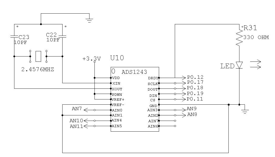
We are interfacing ADS123 with LPC2148 and facing the following problems.

our setup.

vref+ 3.3v
vref- 0v (GND)

AIN1 : Thermistor 30K (Voltage divided by using 1k resistor)
RANGE : 0
UNIPOLAR

When we read ADC value using RDATA, after getting the DRDY low. The value we get is inconsistent.

When read continuously 
                     1. It gives the one reading.
                     2. the second time it display some other reading
                     3. after couple of times it again displays the first reading.

 Ex.   When the ADC value is converted to Deg C using Steinhart–Hart equation I get something like the following

(Output in DEG C )

    34.0
    35.5
    34.0
    32.8

I replaced  the thermistor with a pot and still getting the same result. can some one help me understand where I am wrong.

  • Hi Clarence,

    Welcome to the forum!  Most likely what you are seeing is noise.  To achieve high levels of performance, careful planning and good PCB layout is critical.  Can you send me a schematic and give more detail as to how you have your prototype connected?  Also, is your reference voltage stable?

    You may also want to take a look at using a device like the ADS1248, or ADS1220 and using the current sources within the device to generate the excitation for the thermistor.  You can also use the same excitation to generate the reference.  This will lower the noise and drift by making the measurement ratiometric.

    Best regards,
    Bob B

  • Hi Bob,

    Sorry for the late communication. I was held up in another
    project. My guys started getting results from ADS1243.

    I am getting 0 and full reading for 0V and 3.3V analog input.

    I have connected as follows

    VDD, VREF+ 3.3
    VREF- Gnd
    AIN1 : GND

    Register settings

    ACR 0x44 (i.e)
    UNIPOLAR
    RANGE=1

    all other registers are to default.

    I am using LPC2148 as controller MC crystal is 12Mhz

    I am attaching the schematic


    Sequence
    1. wait for DRDY to go low
    2. set MUX for channel
    3. wait for DRDY to go low
    4. issue RDATA command
    5. read data

    The problem I am facing is, When I give input 1V as analog
    input channel 0 the reading I am getting is not correct.
    When I did the reverse calculation to find the voltage input for the given ADC value using formula

    ADC value = Vi * 16777215 / Vcc

    The Vi is calculated as 2V.

    I think the problem I am facing is while reading from the ADC.

    Can you please let me know where I am wrong.

    Thanks for your help

  • Hi Clarence,

    When using Range=1, the full-scale range changes to +/-Vref/(2*PGA) as is stated in the electrical characteristics table on page 3.  With a Vref of 3.3V and PGA of 1, the full-scale range is +/-1.65V for bipolar mode and for unipolar mode it is 1.65V.  In unipolar mode the LSB weight is 1.65V/(2^24 - 1).  That is 1/2 of what you are using, so your calculations will be twice as big.  One other thing to consider is when you are applying more than 1.65V to the input you are actually applying a voltage more than full-scale and the device will output a full-scale reading.  In the case applying the 3.3V input it will be full-scale, but so will 2.5V, 2V, 1.8V, etc..

    Best regards,

    Bob B

  • Thanks Bob for your quick reply.

    Sorry, my bad. Now I changed the Range bit to 0 and I think I am getting the max value.


    While I am checking out other channels, I noticed that while I am varying my input in channel 0, I am also getting some variations in Channel 7 also.

    I think the problem is while reading the DATA.

    Bob, can you please help me in this.

    Thanks and Regards

    Clarence

  • Hi Clarence,

    From your previous schematic you show AIN7 as not connected.  Do you have a sensor/voltage connected to AIN7? 

    Best regards,

    Bob B

  • Hi Bob,

    Thanks for your reply. Yes, I have connected 30K Thermistor. I am using two(2) ADS1243 the schematic is for the second IC.

    Regards

    Clarence

  • Hi Clarence,

    Unfortunately your are providing very little information as to your problem.  For me to be of much help I need some more detail as to exactly what you have connected (detailed schematic) and what is being applied to the inputs as well as the data results you are seeing from the ADC (raw codes).

    It is possible that you are changing your mux too late to receive a valid conversion result.  If you take a look at diagram 2 on page 6 of the ADS1243 datasheet you will see a time t17.  Following the falling edge of DRDY you have only this window of time for changing the mux to allow enough sampling data to pass through the digital filter for single-cycle settling.  Beyond this region of time you will mix sampling from the previous mux setting with the new mux setting which will give an invalid response.  If you cannot change the mux within this window of time, then you will need to discard the first result after the mux change or use the DSYNC command to reset the digital filter.

    You can find more information on page 10 in Figure 2 and the discussion on Input Multiplexer.  You can reset the digital filter to restart conversion using the DSYNC command.  The DSYNC Operation is discussed on page 14.

    Best regards,

    Bob B