This thread has been locked.

If you have a related question, please click the "Ask a related question" button in the top right corner. The newly created question will be automatically linked to this question.

Question about the ADC12D800RF Reference board:the DCLK_LOCKED LED is not lit

Other Parts Discussed in Thread: WAVEVISION5

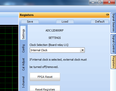
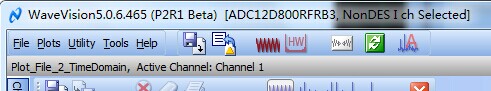
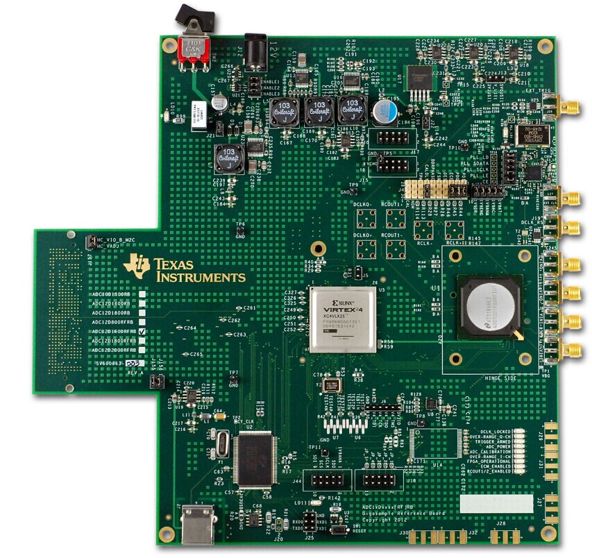
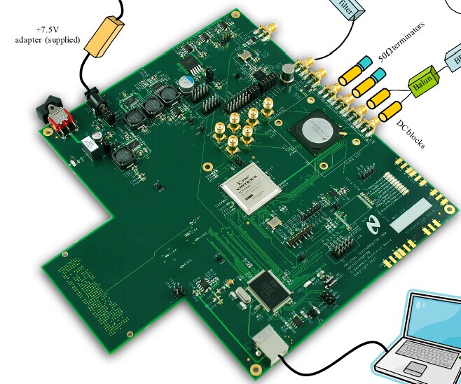
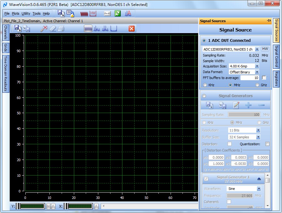
I installed the WV5 software, and followed the user guide to setup the reference board , the software successfully recognized the board, but Why the DCLK_LOCKED  LED is  not lit? And after clicking the capturing data button on the WV5, there is no data display and warning will come out in about 3 minutes.

I have test the input clock to the ADC, it is normal  800MHz. I wonder whether the version of software is not right or some jumpers on the board are needed to configure or some other reasons.

  • waiting for solution.......

  • Hello Tianyi,

    We will need some more information to help you solve this problem. First can you tell us if you are providing an external 800MHz clock through the SMA or whether you are using the onboard clock? If onboard, can you tell us how you are measuring it? Second, can you confirm that power is being supplied to the board? The software will recognize which board is connected even if power is off. There is an on/off switch adjacent to the power connector that is switched off by default. A red LED (LD10) will be illuminated when power is supplied.  You mentioned the DCLK_LOCKED LED is not lit. Can you tell us which adjacent LEDs are lit? We expect the following LED pattern when the proper image has been loaded:

    DCLK_LOCKED ON
    OVER_RANGE_Q-CH OFF
    TRIGGER_ARMED OFF
    ADC_POWER ON
    ADC_CALIBRATION OFF
    OVER_RANGE_I-CH OFF
    FPGA_OPERATIONAL ON
    ECM_ENABLED ON
    RCOUT1/2_ENABLED OFF

    It will also help to confirm which version of the ADC12D800RFRB board you have? Please refer to the following thread for more information: http://e2e.ti.com/support/data_converters/high_speed_data_converters/f/68/p/318256/1107540.aspx#1107540

    Lastly, ensure that you have the latest version of WaveVision5 which you can download from the following link: http://www.ti.com/tool/wavevision5

    Thanks!

  • Hello Tianyi,

    One more thing to try. In the WaveVision5 GUI, navigate to the "Registers" tab on the right side (shown below). 

    Toggle the Clock Selection to "External Clock" then back to "Internal Clock". There could potentially be a timing issue that is marginal in the FPGA code. If this solves the problem, then you will likely need to add some delay in the code to allow the clock to be properly and full programmed before advancing.

  • Hello Luke,

     thank you for your help. I would provide you more information now:  

    1.At the start ,we use the clock on board, and we test the input  differential clock of the ADC using a RS spectrum analyzer.  And afterwards, we conect a external clock , the 800M differential clock is also normal.

    2.We are sure the power is supplied successfully!!

    3.The led pattern is same as the board user guide and the patter in your reply  except the DCKL_LOCKED LED.

    4.We check the version of the FPGA image,it is shown in the following:

    at earlier time, we also doubted if this board is not matched with the FPGA image, but we don't know how to get the right FPGA image even though it is not matched with the board at hand.

    5 Here we would like to give you the picture of our bord : 

    6.the version of WV5 is 5.0.6.465, we don't know if it is the newest,but we only find this version on the websitehttp://www.ti.com/tool/WAVEVISION5 . The web site you provide can''t be opened.

    7.  we have also watch the demo vedio on the website http://www.ti.com/tool/adc12d800rfrb.we foud tha the board is a litte different of ours.The logo is NS, but not TI. It looks like as the following:


    8 also on the website metioned in 7 ,there is  a  ADC12D800RFRB Design Package  we downlowd it ,finding the schematic is not matched with our board. So,we are very  puzzled by the version of board、 software、FPGA image、and design package. 

    9 For one more thing ,why the number on the on board clock PLL is VM AB24E3 4123203 but not LM2531 or LM2541.?We googled the number but found nothing.

    Thank you very much! Looking forward to your reply!

    Tianyi Xiong

  • Hello Tianyi,

    I have attached the design package here:

    8233.ADC1xDxxxx(RF)RB Design Package.zip

    To convert the topside marking on the Clock IC, you can use the part mart lookup tool: http://www.ti.com/general/docs/partmarking/partmarkinghome.jsp

    The device that is on the board is the LMX2541SQ3320E which has a topside marking of 413320E

    Also, it looks like you have the correct version of the WaveVision5 GUI because it recognizes the board as the ADC12D800RFRB3. If you had an older version it would give an error that the device is not recognized.

    To the original question, have you tried toggling the "Clock Selection" in the WaveVision GUI as mentioned above? 

  • Dear Luke 

         I 'm very appreciat the help you give. I had spent much time to  serached responding schematic and design packege to the board we have but failed. Now you provied the right version.And thank you for solving my confusing about the CLOCK IC.

          I had tried toggling the "Clock Selection" in the WaveVision GUI,sorry for forgetting to inform you in the last reply. But the DCLK is also not detected by FPGA. And the sampling rate display on the WV5 is like this(32kHz??):

        Oh, one important thing is: we had doubt the if the amplitude of the differential clock is not enough or is not normal ,because we had tested  the CLK+ is -10dBm and the CLK- is -6.6dBm.And the data sheet of ADC says the min peak to peak voltage of the VIN_CLK is 0.4V(we calculate it as -4dBm, you can have a check.)  like the following, With your experiences , is this input clock  normal or unnormal??

        For one thing,   in the designed packege , there is a FPGA Source folder it is like this(there is no 800RF??):

    and the ISE project in these three folder can not be opened warning there are missing files.

    Thanks!

    Regards

    Tianyi

  • Hello Tianyi,

    The ADC12D800RFRB3 uses the same schematics and layouts as the design package above. Thank you for pointing out the absence of FPGA source code, which I have attached below:

    3122.ADC12D800RFRB.zip

    For the clock amplitude, we specify a limit 0.4Vpp (-7dBm into 100Ω differential load). Since the clock receiver is detecting the zero crossing we expect that it will work below this level, but noise/jitter starts to have an impact on performance so we cannot recommend reliable operation. 

    However, if the board has not been modified then it is unlikely that clock amplitude is the problem. All of the boards we release have been checked for functionality and performance so we would be very surprised to see a hardware failure. 

    As one more check, when you toggle the "Clock Selection" from external back to internal, the "Sampling Rate" may not update until you take a capture. Can you try a capture event and let us know if it still has a time out error?

    Thanks!

  •  Luke ,thank you for providing the FPGA code of 800RFRB.

    We actually have tried many times capturing a data no matter before or after toggling the Clock Selection. When using the on borad clock , it is a time out error ,when using  a externla clock output by a RS signal generator , the WV5 warned the DUT can't detecte a clock.

    One thing I want to know is that If the ADC will start to work after we click the data capture button in WV5 or it will start to work as long as there is a input clock(of  course the configuration has been done by FPGA) .

    According to the user guide and the demo vedio , the DCLK_LED  will be lit after power up linking with PC but before clicking caputuring data button. And with our exprience ,such high sampling rate ADC will be very hot when working ,but it is not .So we doubt maybe there is something wrong with the ADC or something we don't know.

    Thanks 

    Tianyi

    Best regards!