This thread has been locked.

If you have a related question, please click the "Ask a related question" button in the top right corner. The newly created question will be automatically linked to this question.

ADS1232 with external clock

Other Parts Discussed in Thread: ADS1232, ADS1220, REF102, ADS1232REF, ADS1259, TINA-TI

Hi,

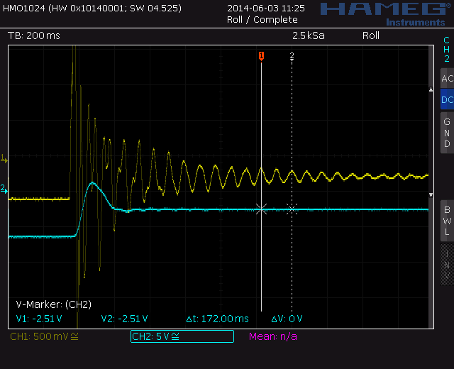
I purchased a REF board for ADS1232. while testing board I figure it out that I have a mechanical vibration around 15hz. 

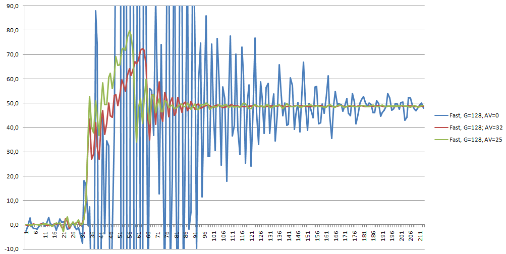
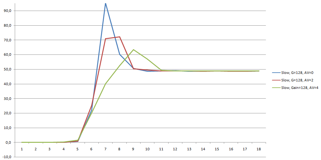
In slow mode I can read weight in 0,7seconds. In fast mode more than 2 seconds. The vibrations are not lineer so I can not average them in fast mode. 

Problem is that slow mode is a bit slow for my application. With the help of an external clock I want to downgrade 80sps data rate to a slower rate. and filter out vibration.

1-) If I divide external clock by 8 and use fast mode. Will I get same noise performance with internal clock and slow mode.

2-) How can I set an external clock so that I will have cut off frequency around 6 hz. What is relationship between cut off frequency and external clock.

3-) How will I check 50Hz and 60Hz rejection with that external clock.

4-) how precise should be the external clock. Is there an application note or something that shows an example.

Thanks.

  • Hi Dogan,

    I'm not quite sure I'm following your logic.  Using the internal oscillator of the ADS1232, you will only get 50/60 Hz rejection at 10sps data rate.  This is because the sinc filter notches occur at the data rate.  15 Hz is not fully rejected at 10sps, although it will be reduced 50dB (as shown in Figure 31 frequency response plots).  You will also see notches at multiples of the data rate (20, 30, 40, 50, 60 Hz, etc.).

    At 80sps, the first notch occurs at 80Hz.  This means that 15Hz (as well as 50/60 Hz, and harmonics) are within the filter passband.

    Slowing of the fclk for the ADS1232 will not make you measurements happen sooner.  The ADS1232 uses sinc4 as the digital filter, which means that it will take four full conversion periods for the digital filter to fully settle following a substantial change in the input.  It would appear that you also have some analog filter settling as well as I would expect the reading to stabilize in no more than 1/2 a second at 10sps.

    Now to answer your questions.

    1. You cannot get the same noise performance by slowing the clock and using the faster data rate. as compared to using the internal clock at the slow data rate.  The difference is related to the oversampling ratio.  What is the same is the notch filters occur at the same frequencies.  I'm not sure what benefit there is to using this method.
    2. The response is sinc4.  I will try to get some more specifics, but why 6Hz?  You can lower the nominal cutoff of high speed by lowering the external clock frequency.  You can raise the nominal of the low speed cutoff by rasing the external clock frequency.
    3. Regarding 50/60Hz rejection, the only way you can get both frequencies rejected is to have a notch at both frequencies.  The only way to notch both is to have the data rate at 10sps.  The only way to check for rejection is to measure it by applying a known signal to the inputs and measuring the output.  One way is by using an FFT.
    4. We do not have any app note related to applying an external clock for the ADS1232.  The filter notches will be directly related to the frequency of the clock and the stability of the clock.  If the clock is off by 10%, then so will the notches.

    You can apply an external analog filter to the inputs for a 6Hz cut off, but this may increase your analog settling time.  One thing to keep in mind is the 15Hz noise will be down about 50dB at 10sps, and every other harmonic will be notched by the sinc filter.  At 80sps, you will get your initial reading sooner, but the reading will be affected by the 15Hz noise as well as 50/60Hz power line noise.

    Another possiblity is to use a device with a higher data rate and a different digital filter that will settle in one cycle.  The overall noise will be higher in these devices, so this will depend on the desired measured resolution.  One possiblility  may be the ADS1220 where you can get 50/60Hz rejection at 20sps.

    Best regards,

    Bob B

  • Hello Bob,

    Thanks for your detailed explanation.

    Let me explain my application in little more detail I guess you can give an idea about which architecture I should follow.

    In my application there is a weighing cup. The product I measure will fell from a distance of 20cm or so to the weighing cup. I must mesure its weight as soon as possible. So there will be mechanical vibration because of the impact from the product I will measure.

    I must use higher capacity load cell because of this impact and because this weighing machine used in industrial environment. Normally we use 10kg or 15kg load cell if our product range is from zero to 1kg. There is no way of getting products over 1kg. The measurement over 1kg is useless. We use 2mV/V load cell. And has OIML certification. Load cell has 4 wires for 10kg and 6 wires for 15kg. I can not change them right now. They are fixed.

    I need to have a resolution of 0,1gr on user display. And my measurements must be around +/-0,1 for the product I measure. That means if 50gr of product fells on cup in 0,5 seconds time I must measure it between 49,9 and 50,1.

    Also I need to have low drift because this design needs to get OIML certification. Maximum it can be 1.4 gr for a 5 degrees of change. It will take 4 hours to measure drift so self heating also must be considered. But if we can get better drift performance it will be better.

    Right now I use Analog devices AD620 and an amplification circuit that I made to increase load cell output to +/-10V. I exicite my bridge with 10V. REF102 IC. I use panasonic A/D converter module. For AD620 I have a gain of 660. And on my analog filter I have a gain of 13. Totally 8500. For 1 kg weight my output changes 17V. So I adjust my AD620 output voltage to -8V with the help of an DAC on ref pin. And If 1kg weight is put on my cup I have 9V on A/D converter.

    I have tested ADS1232REF, yes it has a lot of advantages compared to my current design

    1-) It seems to have lower drift. 

    2-) Settling time of different weights are nearly same. For example 50 gr weight settles in 8 conversions. 250gr weight settles in 8 conversion too. With my AD620 design settling time changes with weight.

    3-) Range is increadable I can measure up to 6.5kg compared to 1 kg in AD620. 

    But if you ask me, I would not switch my design from AD620 to ADS1232 because;

    1-) ADS1232 looks like it is more fragile. I do not how to explain maybe because of digital filtering. With AD620 once the drift stops boards heats up. Drift is nearly zero. It has better vibration rejection because of analog filter.

    2-) Its resolution between zero to 1 kg is approximately similar to AD620. In theory maybe it has higher resolution but in practise mechanical vibrations dominate noise. So in terms of resolution AD620 seems better.

    I guess I need some kind of an amplifier before ads1232. But everyone tells me that I will get a lot of noise. But I really think that obtaining 13 bit or 14 bit resolution can be achievable. With an analog filter before ADS1232 will help a lot on mechnaical vibrations. 

    Let me put ADS1232 output if 50gr product hits on weighing cup.

    This is output of AD620. And output of my analog filter.

    What do you think about this.. Do you think there can be a solution?

    Regards

  • Hi Dogan,

    I appreciate your detailed explanation of your system.  It is very helpful.  The ADS1232REF has the provision for an analog input filter, but the filter resistors are 0 ohm.  You would have to provide resistors of the desired value to achieve an analog filter.  This should help with the vibration frequency.  The analog filter would add some time for the input settling time, and you would not see as quick a response as you do with no analog filtering.

    You could change the clock frequency to notch at 15Hz for the digital filter, but then we would lose the steep notches at 50/60Hz.  I would have to set this up in the lab to see what the actual degradation is with respect to 50/60Hz.  I will also need some more time to look at other possible options or combinations that will work for you.  Now that I know your requirements I can work through a number of combinations.

    Best regards,

    Bob B

  • Hello Bob,

    Is there any idea that you can share with me?

    Regards,

    Dogan

  • Hi Dogan,

    Sorry for the delay as I've had about 10 things going on at once.  You can create at notch at about 15 Hz by using an external clock of 7.5MHz and the low speed setting.  This will allow 50Hz rejection at about -85dB  and 60Hz rejection at -177dB.  This will also notch the 15Hz.  Cutoff frequency in this case is about 3.3Hz.  The data rate will be 15Hz.

    If you want the cutoff at 6Hz, then you will need use the high speed setting of the ADS1232.  To get precisely 6Hz you need 1.65MHz clock.  I think the closest standard value is 1.8432MHz where the cutoff is 6.8Hz.  The data rate will only marginally increase to about 27Hz and the 50/60Hz will be much worse than the previous case.

    I'm still looking into this so I'm not done yet, but this is what I have so far.

    Best regards,
    Bob B

  • Hello Bob,

    I have tested ADS1232REF with external xt. I had 8Mhz in stock so I give it a try. It seems that responce is a little bit faster. It took around 10-12 samples for weight to settle.

    It was like between 7-9 with 4.9Mhz.

    But I am still not happy with the output of the ADS1232. I do not know the reason but It seems that there is a missing chain between loadcell and output of the A/D converter. It is hard to explain some times I make calibration when I remove weight is must return to zero. Some times it does not. display shows 0,3gr. I need push tare button several times. Also there is drift around 0,5 in couple of hours time.

    For example With relatively same temperature environment

    08:00 0,0gr

    10:00 0,5gr

    12:00 0,6gr

    14:00 0,3gr

    next day I set up same experiment and drift is maybe 0,2 or 0,3 at 12:00. For a fixed period of time like 15 minutes everything seems OK. But It is like 0,3 gr shift on zero time to time and it seems it happens randomly.

    Regards,

    Dogan

  • Hi Dogan,

    If you are using the ADS1232REF, there are some things to consider.  First of all the analog input filtering is not present on this board unless you have replaced the 0 ohm resistors at the analog inputs.  Second, the firmware was not designed for long term measurements (drift), but rather for demonstration purposes only.  To compensate for offset drift, the self-offset calibration should be issued periodically.  The ADS1232REF only does this once at powerup.  Also, the firmware in scale mode is not designed to be operated in conjuction with the GUI or console functions.  You cannot determine settling response in the scale mode, so I'm not sure how you are collecting the data nor if the data is being collected properly.  To operate this device properly you should either create your own prototype or use the ADS1232REF in analysis mode only.

    Best regards,

    Bob B

  • Hi Bob,

    I do the following in order to test settling time.

    I switch to analysis mode and set a file to store A/D output. I press record. Wait for couple of seconds and put 500gr weight and wait for couple of seconds, remove 500 gr weight and wait for couple of seconds more. Than I discharge the weight on the weighing cup. Wait couple of seconds and stop the recording.

    I transfer datas to excel. average 30-40 values in order to find zero weight output. Average 30-40 values to find output at 500gr weight.

    If at zero weight average is 1000000

    and for 500gr weight average value is 1500000

    (1500000-1000000)/500=1000 change for 1 gr.

    if my A/D value is 1250000

    1250000-1000000= 250000

    250000/1000 => my weight is 250gr

    If I make a formula for excel I get the weight for each sample and since I discharge a known weight I can trace settling time.

    I will do my own ADS1232 board there are questions for that board too but...

    Have you check any other alternative especially with instrumentation amplifier. I still think that and alternative with instrumentation amplifier and a SAR or delta sigma adc can perform better.

    Regards,

    Dogan

  • Hi Dogan,

    This is not a fair comparison.  If you are using 30-40 averages to determine the 0 weight and added weight, you are averaging out the noise of the measurements.  You should use the same criteria for settling which should be 30-40 averages.  This will increase the settling time even more.

    To try and explain this in a little more in detail, when you have an increased number of averages you are reducing the level of noise in the measurement.  When you do the settling time measurement, you are expecting to reach the lowest level of noise with a fewer number of samples than you used to find the 0 point.

    There are a number of factors that determine the real settling time.  One is analog settling of any filter that may be used.  The second is the response time of the load cell itself.  The third factor is the settling time of the digital filter.

    When determining the settling time, you need to consider the above 3 factors and the noise.  Early on you stated that you have a vibration on the order of 15Hz.  This noise must also be considered in the final solution, as well as any high frequency noise or power line cycle noise.

    If you consider just the noise at DC, the noise will be related to the stability of the reference, the noise of the sensor and the noise related to conversion (made up of quantization noise and noise of the signal through the PGA).  An advantage of the Delta-Sigma over the SAR is in the power of modulator to shape the noise.  The Delta-Sigma will oversample the input (at the modulator frequency) and filter the response to remove a portion of the quantization noise.  You can oversample a SAR (and average), but you will not shape the quantization noise.  The Delta-Sigma will shape the noise so that the noise is lowest near DC and increases into the higher frequencies.  The digital filter of the Delta-Sigma creates a low pass filter to remove the higher frequency noise component.  The lowest noise on a Delta-Sigma is at 0V input (shorted input).  The level of uncertainty increases as the input voltage approaches the reference voltage value.  A noisy reference will affect the noise of the conversion result.  However, if you make the measurement ratiometric, where the reference and the sensor excitation is the same, the noise can cancel as well as drift of the reference.  This happens due to a cancellation of the voltage terms in the transfer function and the conversion becomes a ratio of the changes of the sensor relative to a value for full-scale output.

    The value in using the built-in PGA over that of external only gain is in the lowering of input referred noise as gain is increased.  Another advantage is with the ability to easily make the measurement ratiometric.  The value of using an external gain is in having the ability to tailor the gain to a specific value relative to the operational range.  However, the noise may increase dramatically depending on components used and making the measurement ratiometric becomes much more difficult.

    So in the end you will need to determine which method or combinations will work best for you.  If you need a multi-pole filter with gain, it may be more convenient to use external amplifiers.  If you use this type of method, you would want to use the ADS1232 at a gain of 1, or perhaps the ADS1259 if you need a faster data rate.  You can see the typical noise tables in the respective datasheets.

    If you download the free simulation tool, TINA-TI, you can simulate the performance of the filter design and the total noise of the input stage.  This combined with the noise of the converter will give you an idea of performance relative to noise.  Once you have determined the noise component, you can look at the other factors as they relate to the settling time.

    http://www.ti.com/tool/tina-ti

    Here is a link to the tool to help with designing filters:

    http://www.ti.com/tool/filterpro

    Best regards,

    Bob B