This thread has been locked.

If you have a related question, please click the "Ask a related question" button in the top right corner. The newly created question will be automatically linked to this question.

Problem with Message Communication protocol V3.0

Other Parts Discussed in Thread: AFE4400SPO2EVM

Hello,

I am using AFE4400SPO2EVM board with AFE44x0SPO2EVM GUI version 2.0 and upgraded the firmware version1.3.

After these changes I verified the EVM kit working with GUI2 version and the captured the signals with continuous which then were showing better plots of IR,Red,Ambient red,Ambient IR

I am now trying to get continuous data from EVM using this as said in the message communication protocol version3 pdf

For continuous data, PC sends 0 as the number of the packets.

Example: to capture continuous data, PC sends: “0x01 0x2A 0x00 0x00 0x00 0x00 0x0D”

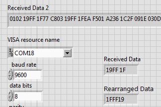
I am sending the above data from Labview using these baudrates of 9600,115200,230400 which resulted in these

1)The received data is following the format as it should be but the IR,Red are being constant as 1FFF19(after rearrranging them in order of LSB and MSB)  but whereas the others are changing.

2) I don’t know why the LED1 (Green) and LED2 (Blue) are constantly in ON state on the EVM hardware.

Another observation: When I used the same setup and sent the message as “0x01 0x2A 0xFF 0xFF 0xFF 0xFF 0x0D” (this is for the before version of message communication protocol).Only LED1 is constantly ON in this case with the IR,RED in the received data still the same.

Can someone explain me reasons for these and is the baud rate is set to 230400(as Praveen answered this here http://e2e.ti.com/support/applications/high_reliability/f/30/t/351691.aspx )

in the microcontroller with firmware version3 and should I same in the labview as well.

  • Govardhan,

    Thank you for you post. We hope to get back to you with an answer shorty.

  • The AFE registers configured through the firmware are different than the AFE registers configured through the GUI.  You will need to configure the AFE with the EVM GUI default register values in your labview code.

    In the firmware, LED1 (Green) indicates the data transfers from the ADC registers for the ADC register read command. 

    LED2 (Blue) indicates the commands (AFE config and other commands) from the GUI.

    For the LEDs, you should notice the same behavior that you see when you are using the EVM with the GUI v2.

    If you notice a different behavior, then there is some problem with your labview code.

  • Hello Praveen,

    Thanks for your suggestions.

    I think my Labview code is working fine because

    1)When I send this 0x01 0x2A 0xFF 0xFF 0xFF 0xFF 0x0D(as said here http://e2e.ti.com/support/applications/high_reliability/f/30/t/350615.aspx

     for nearly continuous data capture) to the EVM it is showing only LED1 ON which is same using TI-GUIversion2

    2) When I use 0x01 0x2A 0x00 0x00 0x00 0x00 0x0D (as said in mesg commn protocol v3 pdf for continuous data capture) from my Labview both Green LED and Blue LED are but when I use the TI-GUI version2 only one green LED is constantly ON.

    I think this 0x01 0x2A 0x00 0x00 0x00 0x00 0x0D command for continuous data capture won’t work. Can you please help me out in figuring out this problem.


    But I am still not clear with the below. Can I get answers for these

    1) What (is it 0x01 0x2A 0xFF 0xFF 0xFF 0xFF 0x0D or anyother ) to send from Labview to capture the continuous data if the EVM kit has been upgraded with firmware version3.

    2) When I used this 0x01 0x2A 0xFF 0xFF 0xFF 0xFF 0x0D with EVM firmgradeV3 it is showing a constant value of 1FFF19 for both IR,Red channels.

    3) What is the baudrate that is used in GUI version2 and what is it in the EVM kit.What should I use in my Labview to capture continuous data.


  • Seriously, I am facing problem with the new message communication protocol of version3.

    Because I observed this behavior many times

    1)When the EVM kit has upgraded with firmwareV1.2, I am able to see the varying values of IR, Red and other channel values as well in Lab view when “0x01 0x2A 0xFF 0xFF 0xFF 0xFF 0x0D”  is sent form lab view and it is behaving the same with these baudrates 9600,115200,230400.

    2) When the EVM kit has been upgraded with firmwareV1.3, The values of IR,Red are being constant at 1FFF19(after rearranging them in order of LSB and MSB)  when this value 0x01 0x2A 0x00 0x00 0x00 0x00 0x0D si sent form Labview for capturing continuous data has said in protocolv3.0.

    Can someone help me out in figuring the problem with this new version3 as I need to get continuous data to plot the realtime data of IR channel signal and detialed explanation about the baudrate thst should be used in my Labview.

  • You have to read through my previous posts regarding why the values of red and IR are constant. The two firmware V1.2 and V1.3 have different TIA gain settings. You will have to reprogam the AFE registers to the GUI default register settings. 

    Regarding the baud rates, the firmware running on the MSP430 microcontroller has a USB stack implemented as a Communication Device Class (CDC). A CDC device supports a range of baudrates. The CDC device is used to emulate a serial port providing a virtual COM  port interface. When the USB client (LabVIEW or hyperterminal) sets the baud rate, the CDC host (EVM) sets the specified baud rate in the firmware. In your labVIEW code, you can set the baud rate to 230400.