This thread has been locked.

If you have a related question, please click the "Ask a related question" button in the top right corner. The newly created question will be automatically linked to this question.

ADS1148 IDAC1 e IDAC2

Other Parts Discussed in Thread: ADS1148

Hi,

I'm configuring ADS1148 to enable pin20 and pin19 (IEXC1 and IEXC2).
I have this problem:
- Configure with MUX1 VREFCON = 01
- Configure IDAC0 with IMAG = 110 (1000uA)
- Configure with IDAC1 I1DIR = 10x0 and 10x1 = I2DIR

I read an output current greater than 1000 uA (about 1,316 uA). What am I doing wrong?

thank you

  • Hi Fabio,

    Have you read back the register readings to verify that they are correct?  How are you determining the current?  One possibility of error can be by assigning both current outputs to the same output pin by mistake.  In this case you would expect 2mA, but if the load has enough resistance to place the total voltage drop outside of the IDAC voltage compliance, then the current would be less.

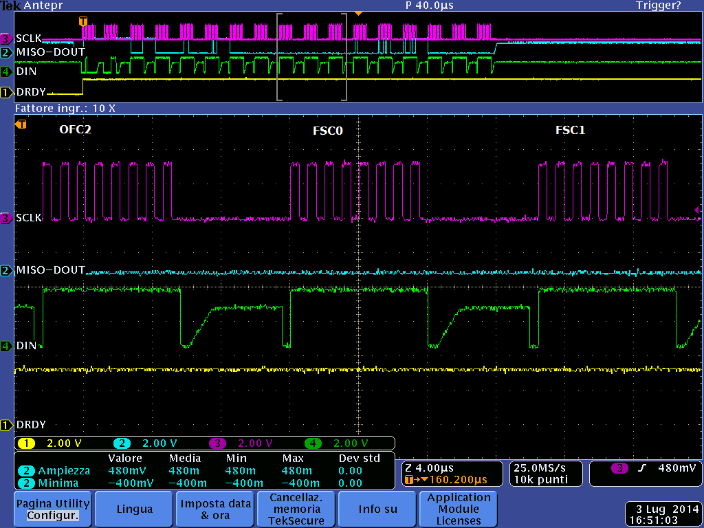
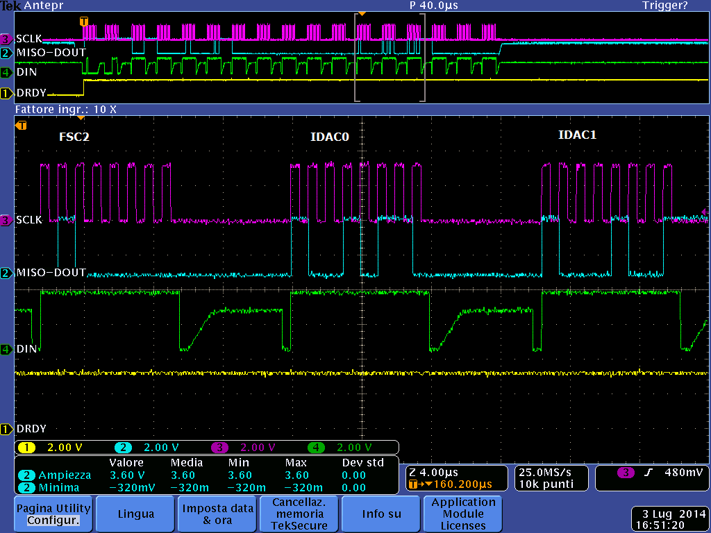
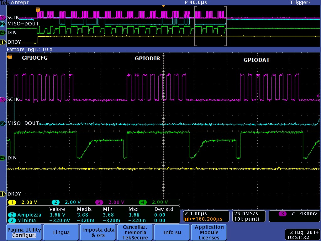
    What are the actual values you used for the IDAC register settings?  Do you have scope/logic analyzer shots of the communication that you can send me so I can verify the communication?

    Best regards,

    Bob B

  • Hi,

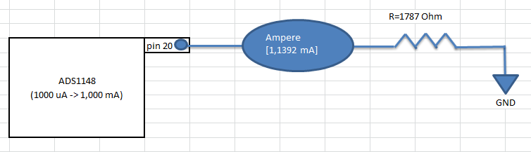
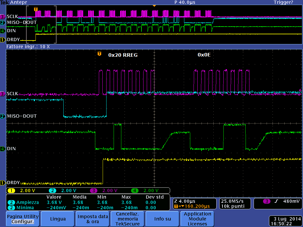
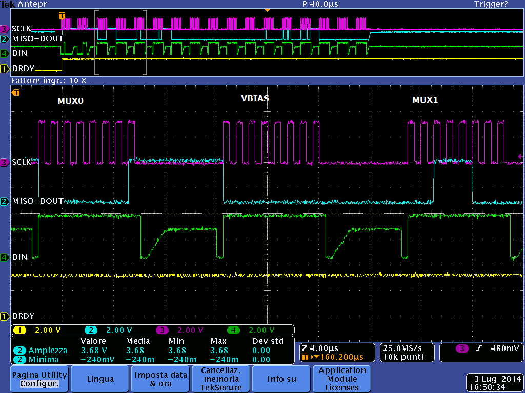
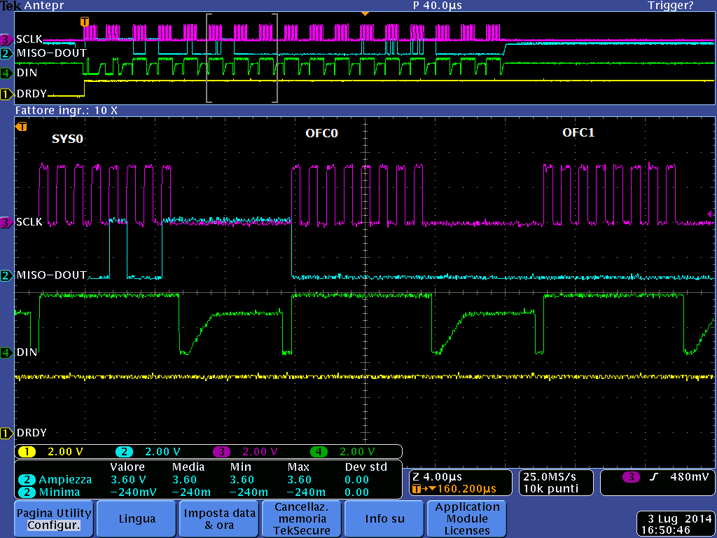
    I put in attachment as I am measuring the current, the response of SPI with all registers.

    MUX0.........01
    VBIAS........00
    MUX1.........38
    SYS0.........09
    OFC0.........00
    OFC1.........00
    OFC2.........00
    FSC0.........00
    FSC1.........00
    FSC2.........40
    IDAC0........96
    IDAC1........89
    GPIOCFG......00
    GPIODIR......00
    GPIODAT......00

    thanks

    fabio

  • Hi Fabio,

    The scope shots look ok.  What supply voltage are you using for the AVDD/AVSS supply?  Have you measured the voltage across the resistor to verify that the current meter measurement matches the current through the resistor by calculation?

    One other thing is there must be a cap across VREFOUT and VREFCOM and VREFCOM should be tied to AVSS.  This cap keeps the internal reference stable.  This is important as the internal reference is used to establish the IDAC current.  Also make sure that you do not have anything that can interfere with the internal reference.  You have assigned the internal reference to connect to the REF0 input.  I would suggest changing the bits in the MUX1 register so that the REFSELT bits are 10 instead of 11.

    Best regards,

    Bob B

  • Hi,

    I change MUX1 and now i have REFSELT = 10

    AVDD = 5 Volt (4.998 V measured)

    DVDD = 3.3 Volt (3.351 V measured)

    The capacitor between VREFOUT and VREFCOM (10 uF) = 2.047 Volt (measured)

    i have R=1787 (measured) Ohm, I=1.1392 (measured) mA V=2.041 (measured) Volt.

    In this configuration the pin 5,6,7,8 (REFP0,REFN0, REFP1, REFN1) are not connected. Is that correct?

    thanks,

    fabio

  • Hi Fabio,

    When using the internal reference, you can leave the external reference connections open, or not connected.  As I don't have your full schematic, I can't say too much more about your configuration. 

    It appears that the internal reference is stable, and you should get the correct output current.  Have you tried any of the other current output values to see if you get similar behavior?  Is the ADS1148 on a protoboard, or is it on a PCB?

    The ADS1148 is factory tested to provide output current within a min/max value of +/-6% of full scale.  This equates to 60uA for 1mA full scale.  The values you have been seeing are well outside the expected.

    In the original post you said you measured 1316uA, but in the last couple posts you measured 1139.2uA.  Was the first one a typo?  Make sure you have good ground connections, and that all your voltage measurements are refernced to the same ground point.  Also make sure that the IDAC compliance voltage is not exceeded.  The total voltage drop created by the IDAC source/load must be less than AVDD-0.7V.

    It is also possible that the ADS1148 has been damaged.  Have you tried another device?

    Best regards,

    Bob B