This thread has been locked.

If you have a related question, please click the "Ask a related question" button in the top right corner. The newly created question will be automatically linked to this question.

ADS5263

Other Parts Discussed in Thread: ADS5263, ADS5263EVM

Hallo!

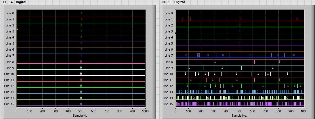
I am just sitting at ADS5263 EVM board tied up to Sparta-6 FPGA and try to connect these two. While observing the oscilloscope with fs = 2 MHz (low to get a good picture of all edges on the signals), I would to ask about the observed bahaviour:


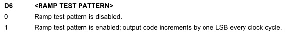
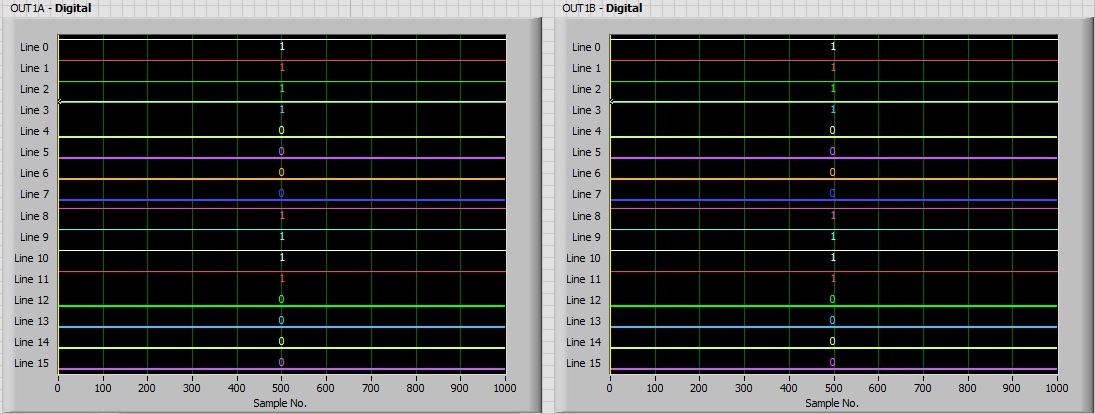
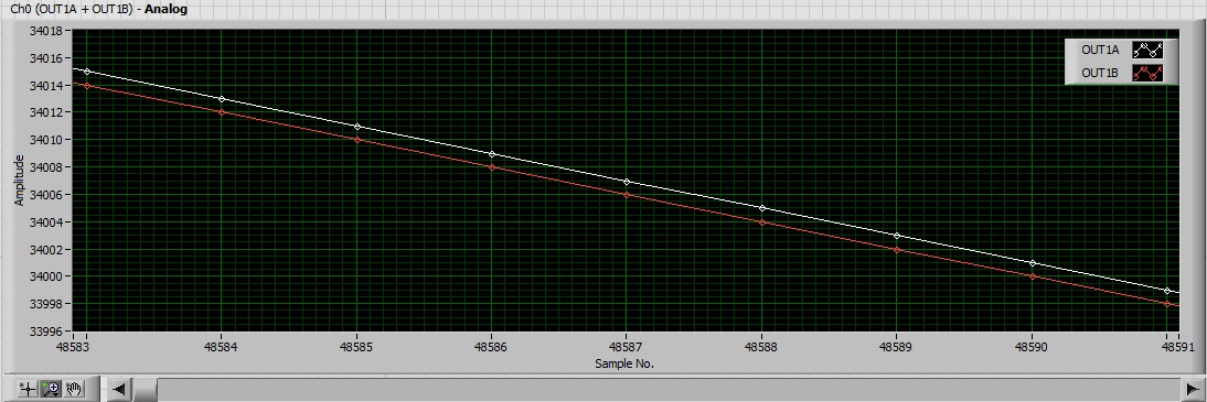
I see that the SYNC-PATTERN on OUT1A is always like 0xF0F0. My question, why does the pattern keep changing. I believe that in the WORD-WISE mode I should get a full sample within one period of of ADCLK clock. The settings are like this (ADS5263 EVM GUI app):

1a)ENABLE WORD-WISE CONTROL is ON

1b)2-wire 0.5x is switched into "0.5x Frame clock"

1c) Mapping of the channels is OFF

1d) LSB-First mode is selected

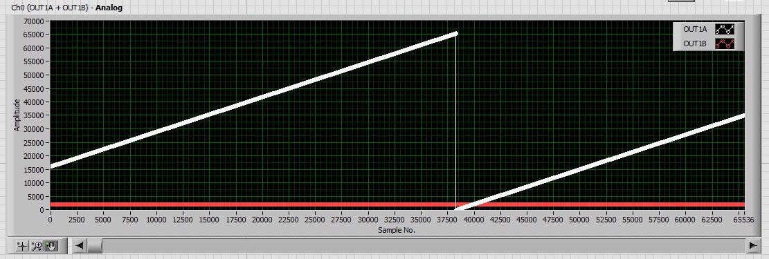
However, when I switch into "1x FrameClock" mode (I assume that I go into 1-wire mode doing this) I see that the pattern is like 0xFF00 -- as it should be.

What do I do wrong? Does the sync pattern deas depend on the 1-, 2-wire selection?


Regards


Pawel

  • Hello Pawel,

    We have received your inquiry regarding the ADS5263 and hope to have some answers back to you shortly.

  • Hi,

    First of all, the Fs you are providing, 2MHz, is outside the specification for this device.  The Fs_min is 10MHz as stated on pp 8 of the datasheet.  However, this does not explain your observations.  

    Regarding your observations, I have confirmed I am seeing the same using the TSW1400 capture card.  Since the RAMP test pattern appears correct in the same mode I think the firmware is OK.  I need to confirm with the design team why sync pattern is not 0xFF00 for 2-wire word wise.  I will get back to you once I close the loop with them.

    Thanks.

  • Hi,

    We are still looking into this observation and hope to get back to you early next week with an explanation.  

    Thanks.

  • Hi!

    Thanks for the reply. Sure I am interested in finding an explanation for the observed behaviour. I was off for a short vacations, hence I was not replying. My suspiction is -- based on the analysis of the Verilog firmwave for TSW1250 -- that the ADS5263 does some word jugglery when working in the 2-wire mode, which is not needed when 1-wire mode is used. Anyway the code systematicaly shifts selected bits when working with ADS5263. I can copy this behaviour into my deserializer, but...

    If you could provide some hints here, that would be welcome. Otherwise I will need to carefully prepare some systematic description of the behaviour in various modes (1-wire, 2-wire BYTE-WISE, 2-wire WORD-WISE for different settings of the mapping register 0x42) on my own. This can be done, sure, but maybe such info could be put in the ADS5263 docs (or better in the ADS5263 GUI docs) so that each individual developer does not need to repeat such experimentation.


    Many thanks for the reply, again


    Regards

    Pawel

  • Hi Pawel,

    Sorry for the delayed response.  I don't think this "jugglery"  is global to 2-wire mode.  Rather, I think there is a problem for the SYNC pattern in 2-wire WORD-WISE mode.  As far as I can see, all other test patterns and captures are correct so the problem is limited to this configuration.

    The design team has not yet confirmed that this is in fact the design implementation but all indications are that it is.  I am told they will know early next week.  If confirmed, we will update our datasheet to mention this.  So, at present, there is no documentation describing this.  I will get back to you once all is confirmed from design team.

    Thanks

    Christian

  • Hi Pawel,

    In 2-wire WORDWISE mode, one would have expected to capture 0xFF00 for a SYNC test pattern per the datasheet Figure 71.  However, we have observed  0XF0F0 instead.  We have confirmed that the digital design matches this observation.  This was done intentionally so that the SYNC test pattern frequency always remains equal to the input clock frequency.  We will document this in our next update to the datasheet.

    Thanks again for pointing out the discrepancy.

    Regards,

    Christian

  • Dear Christian,

    Many thanks for the cheking this up and brining the issue uo during preparation of a new release of the datasheet. In the meanwhile -- I am more and more multitasking, hence the delay -- I was again playing the the ADS5263 EVM board and a Spartan-6 chip with my deserializer running (all hooked-up to LabView for display). I detected odd behaviour of the ADS when operated in the RAMP PATTERN mode.Here is the question

    My question: Is this possible at all that my ADS5263 operated in the RAMP PATTERN mode actually is generating data that DECREASE (instead of increasing, as suggested in ads5263.pdf, p. 25)?

    Here is the description of experiments done:

    I am using the ADS5263EVM software to change the op. mode in the ADS chip. I am using WORD-WISE mode, 2-wire serialization, and analysing channel 1, only. Offset Binary format is selected, but this setting does not affect the operation of the chip in test modes -- IMHO. Everything looks fine with a SMALL exception (vide #3):

    1) here is my SYNC PATTERN (just selected 1000 samples out of 128MB block collected in one go)  data appearing in OUT1A i OUT1B are as they should be (Ox0F0F):

    2) when I switch into the 1-wire mode, then again I get the correct stuff (0x00FF on OUT1A, and trash on OUT1B):

    3) However, when I swith into the RAMP PATTERN, what I got for the 2-wire is this:

    and a close-up:

    Well, this looks fine, OUT1A and OUT1B are monotonically changing, since this is WORD_WISE mode, the they change by 2, but OUT1A is odd, while OUT1B is even. Fine... but according the the datasheet, the RAMP PATTERN produces data that should INCREMENT. What I see is that they decrease!!!

    To eliminate any possibility that my FIFO's, DRAM's are reversing the colleced data before sending it to the PC, I run a simple experiment: I was analysing the ADS data, but instead of using the samples from ADS I was using FPGA-generated data coming from a simple counter. Except for the source of the data, everything else in the code was unchanged! Here is the result:

    When the data are coming from myself (and they are 100% increasing -- I generate them this way), what I get from the FPGA is also increasing. In my opinion this proves that my data-pipes are working fine.

    My question repeated: Is this possible at all that my ADS operated in the RAMP PATTERN is generating data that DECREASE (instead of increasing)?

    I will appreciate hints and suggestions.

    Regards

    Pawel Kopyt

  • Hi Pawel,

    I think it is highly improbable (although I wouldn't say impossible) that the device RAMP test pattern is changing.  I  actually managed to capture exactly the same decremented RAMP test pattern on another LVDS device which only supports 1-wire mode.  This was achieved when I inadvertently inverted the positive and negative Frame clock pins to the receiver.  Can you try swapping these pins on your deserializer?  Finally, you mention providing a test pattern from within the FPGA to check for inversions.  Does this test pattern bypass the front-end deserializer?


    Regards,

    Christian

  • Hi Christian,

    Many thanks for the response and thanks also for the suggestion.

    > Can you try swapping these pins on your deserializer?

    Yes, I tried to swap them. This resulted only in a change in the order of the LSB/MSB received by the PC. When I corrected for this, I again got my RAMP but decreasing.

    What is interesting is that the period of my ramp signal is exactly as it should be -- 65536/2 (the decrease is by 2). If it were some jugglery with lo/hi bytes I doubt if the period would be preserved. Do you agree?

    Also, looking at your data, it seems that you were working with 14b device probably, and by playing the Frame CLK, you got also a signal that is decreasing by 4 (while in the very beginning it should increase by 1 -- is that correct?). what puzzles me is that in my case I got signals exactly as they should by (period, the chage per sample), but the direction is opposite...

    > Does this test pattern bypass the front-end deserializer?

    The data at the end were coming from a counter (and not from the deserializer), but the clocking signal was coming from the ADS.

    Regards

    Pawel Kopyt