This thread has been locked.

If you have a related question, please click the "Ask a related question" button in the top right corner. The newly created question will be automatically linked to this question.

ADS1258EVM not receiving data back through SPI on data out line

Other Parts Discussed in Thread: ADS1258, ADCPRO

Hello,

I am using the ADS1258EVM board to evaluate the ADS1258 for future projects and I have three of these boards built into three separate prototype units using the PIC32 USB Starter Kit and communicating through SPI.  Initially, all three prototype units worked correctly including acquiring data and setting and reading registers.  One of these units is no longer getting data back through the MISO line (Data out on the ADS1258EVM) and I have not been able to determine the cause of the problem.  All the SPI data looks correct going into the SCK and Data In (MOSI) line on J6 of the ADS1258EVM but the Data out line on J6 remains low even when disconnected from the MISO line on the PIC32.  I replaced the ADS1258 with a new one and received the same result.  Both of these ADS1258EVM boards acquire data correctly when plugged into the MMB0 board from the PDK and running ADCPro software.  Attached are some screen shots (please excuse the screen photographs as my scope will not directly output screen shots) and are described as follows:

Photo 1 -  Register write 0A to Config0  ch1-SCK J6-3, ch2 Din J6-11; ext trigger on CS going low.

Photo 2 - Same as above but closeup of data to better view the timing

Photo 3 - Register read command to Config0 - same pin connections as above

Photo 4 - Closeup of above to show timing

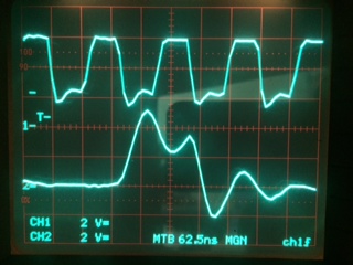
Photo 5 - Register read command as above but looking at Dout J6-13

Photo 6 - ADS1258EVM in MMB0 board acquiring data  Ch1 SCK, Ch2 Dout

Again, the prototype unit that now shows the above problem was initially working and the ADS1258EVM from that unit still works correctly in the MMB0 with ADCPro software.  Thanks very much in advance for any help you can give me.

Bob Jarratt

  • Hi,

    In the previous post, only one of the photos was included.  Attached is a zip file which should have all six photos.

    Thanks,

    Bob Jarratt

    ADS1258EVM photos.zip
  • Hi Bob,

    Thanks for re-uploading the oscilloscope shots!

    You are not trying to control the ADS1258EVM while it is connected to the MMB0, correct?

    SPI and Jumper Wires

    I don't see any problems with you SPI commands. What does your setup look like and where are you probing the SPI signals?

    If you are using jumper wires, SPI signals may get distorted. They might look okay near the microcontroller pins, but near the ADC pins they can might look completely different. When prototyping and wiring multiple boards together, make sure that...

    • Both boards are referenced to the same ground potential.
    • Jumper wires are short.
    • Reduce wire loops (Try wrapping your jumper wires around your ground wire to reduce loop area and inductance).
    • You may even need to shield your setup if you're in an noisy environment.

    EVM Configuration

    Is it just the one EVM that is not responding? If your setup is consistent between the three boards and you are issuing the correct /CS signal? How do you have J3 and J4 jumpers set?

    I recommend probing the other digital signals on the ADS1258EVM and make sure you're not accidentally holding the part in power-down mode (for example). Also check the J3 and J4 jumpers.  The /CS signal is routed through J3. I did not see /CS in the oscilloscope screenshots...Make sure it is held LOW for the entire SPI transaction, and that your microcontroller is not using an SPI slave mode that toggles /CS with each byte sent.

    Best Regards,
    Chris

  • Hi Chris,

    Thanks very much for your prompt reply and help in resolving this problem.  After following your advice and checking the digital signals on the ADS1258EVM board, I found that J6 pins 19 (GPIO5) and 20 (SDA for I2C) were shorted.  Also, the power supply fuse for the analog+5VDC supply was open and no +5 Volt analog was present.  No other issues were found.  After correcting these issues, the system then worked correctly – sets and reads registers correctly and acquires data.  I’m not sure what either of these had to do with SPI operation, but I’ll take the results.

    For sake of completeness, I want to answer the questions you raised in your response.

    1.  You are correct that I am not trying to control the ADS12658EVM while it is connected to the MMB0 board.  I only showed operation with the MMB0 and ADCPro to confirm the ADS1258EVM was still functional.

    2. I have attached a prototype system block diagram to help explain the setup.  I have the ADS1258EVM mounted to a Vector board with a split ground plane on top – analog and digital – by mating connectors for J5 and J6.  This gives me access to power for the board through J5 and chip select, digital ground, SCK, MOSI and MISO for the ADS1258.  I use shielded lines (RG-178) to connect signals between the ADS1258EVM and the PIC32 board for SCK, MOSI and MISO  with shield connected to the digital ground plane at the ADS1258EVM.  Chip select is unshielded.  I also have a 56pf cap on the SCK line and 22pf caps on the MOSI and MISO lines.  The lines are approximately 6 inches long.

    3. Both the ADS1258EVM board and the PIC32 board are referenced to the same ground at the power supplies.

    4. I tried a second ADS1258EVM board with the same result before the issue was resolved.

    5. Chip select was not shown because I can only capture two traces with my scope but I am triggering on CS going low in all the scope traces of my prototype and when I do capture the CS and SCK line the CS line goes low well before the rising edge of the first clock pulse and goes back high after the last clock pulse.

    6. J3 and J4 jumpers remain in the default configuration:  J3 Pins 9 and 11 are jumpered to allow CS to be accessed at J6-7 and J3 pins 8 and 10 are jumpered.  On J4, the only two pins not jumpered are the +1.8V selection pins.

    7. The PIC32 SPI is in master mode.

    I would like your advice on the small caps I am using on the SPI lines SCK, Din (MOSI) and Dout (MISO).  They were added when I had a different setup for the SPI lines in the PIC32 which yielded a different phase relationship between SCK and the MOSI and MISO  lines.  I needed them for reliability at the time and thought this was to suppress noise.  Now I am not so sure.  I have included a screen shot of the SCK and MOSI lines while issuing a Register Write to Config0 with the previous setup.  To me, the new setup shown in the previous set of screen shots seems to more closely match the timing requirements of the ADS1258.  I would appreciate your thoughts.

    One more question:  Is the ADS1258 still your recommendation for new designs requiring a high precision 16 channel 24 bit A/D converter?

    Again, thank you very much for your help and let me know if you have any questions.

    Bob Jarratt

    ADS1258EVM system info.zip
  • Hi Bob,

    Good find and thanks for the details!

    Robert Jarratt said:
    I would like your advice on the small caps I am using on the SPI lines SCK, Din (MOSI) and Dout (MISO).

    I think adding small capacitors is a good idea. They can help reduce fast digital signal edges that can couple into the ADC. It looks like your old setup had more overshoot without the capacitors, so they seem to be effective.

    There are other techniques you could also look into, such as treating the signal traces as transmission lines and using matching to reduce signal reflection. However, for slower interfaces (like SPI) this is usually not necessary. Making sure you have a clean layout with a ground plane directly below your signals traces should maintain good signal integrity.

    Robert Jarratt said:
    Is the ADS1258 still your recommendation for new designs requiring a high precision 16 channel 24 bit A/D converter?

    Yes! Usually when a product is not recommended for new designs, it is because we have a better alternative and I don't have a better recommendation for you at the moment! You can also refer to our o obsolescence policy here.


    Best Regards,
    Chris