This thread has been locked.

If you have a related question, please click the "Ask a related question" button in the top right corner. The newly created question will be automatically linked to this question.

AFE4400 LED on/off wave problem

Other Parts Discussed in Thread: AFE4400, AFE4400SPO2EVM

Hello:

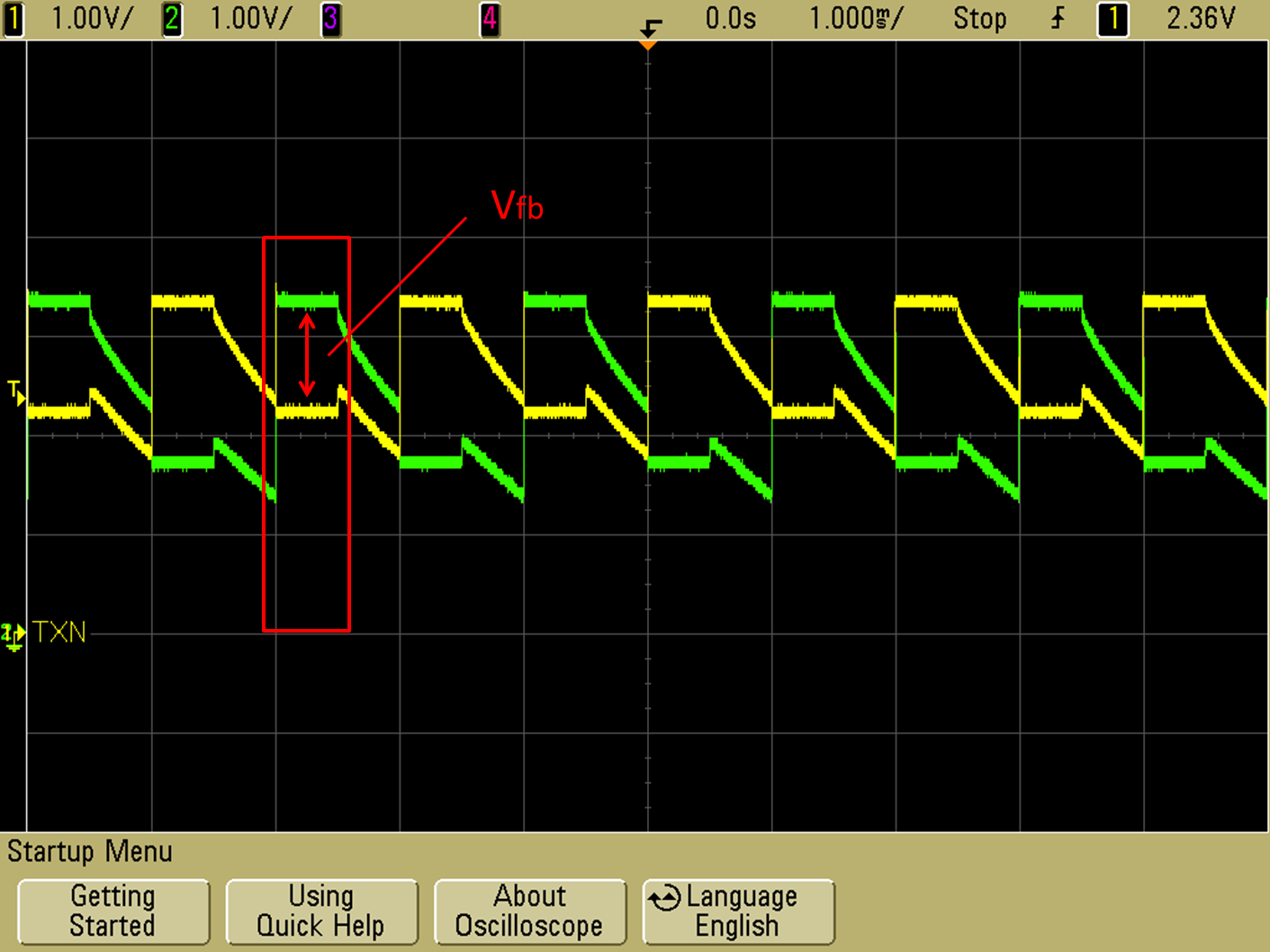
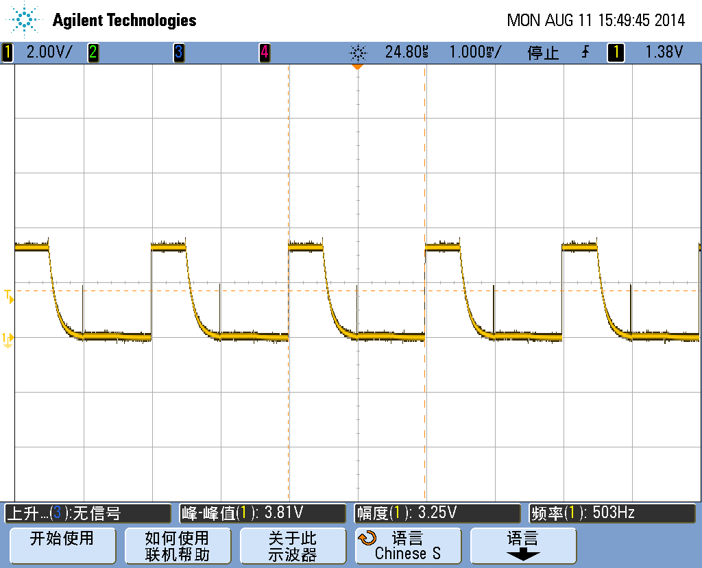
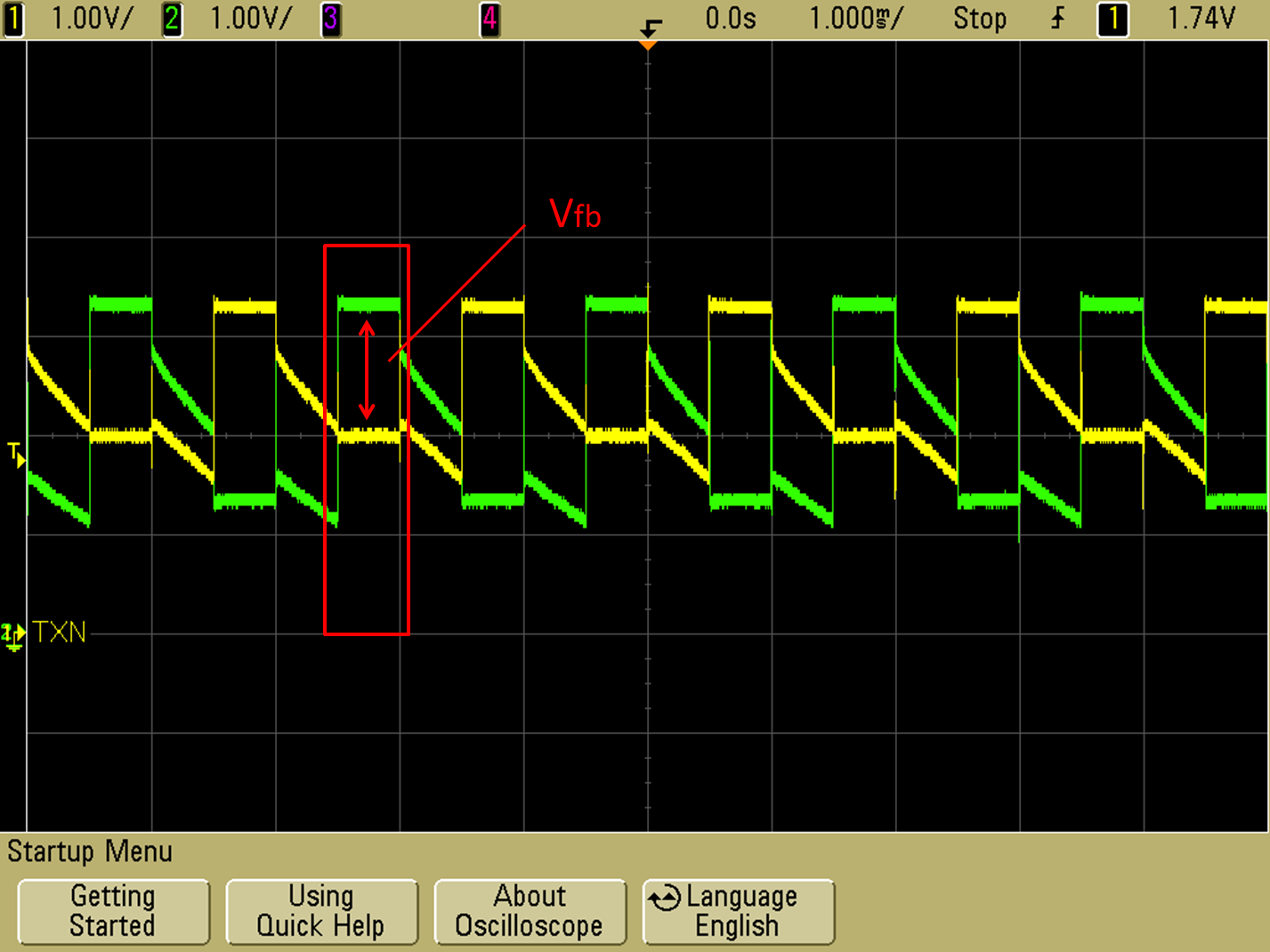
  AFE4400 LED on/off wave is different with the( slau480c.pdf)?the register is configured as the AFE4400SPO2EVM.

what's the problem?

  • Hello Minsun,

    We have received your inquiry regarding the AFE4400.

    Can you provide more information on the four waveform plots?


    Regards

    Praveen.

  • fig.1 fig.2 at TX_P (TP23) and TX_N (TP17) without sensor;

    fig.3 fig.4 at TX_P (TP23) and TX_N (TP17) with sensor;

    page 38 of the slau480c.pdf. 

  • sorry,

    fig.1 fig.2 at TX_P (TP23) and TX_N (TP17) withsensor;

    fig.3 fig.4 at TX_P (TP23) and TX_N (TP17) without  sensor;

    page 38 of the slau480c.pdf. 

  • power is normal.

    the register setting:

    #define LEDCNTRL 0x22
    #define LEDCNTRL_VAL (0x011414ul)

    #define LED2STC 0x01
    #define LED2STC_VAL 0x17C0 // for 500HZ - 6000

    #define LED2ENDC 0x02
    #define LED2ENDC_VAL 0x1F3E // for 500HZ - 7998

    #define LED2LEDSTC 0x03
    #define LED2LEDSTC_VAL 0x1770 // for 500HZ - 6000

    #define LED2LEDENDC 0x04
    #define LED2LEDENDC_VAL 0x1F3F // for 500HZ - 7999

    #define ALED2STC 0x05
    #define ALED2STC_VAL 0x0050 // for 500HZ - 0

    #define ALED2ENDC 0x06
    #define ALED2ENDC_VAL 0x07CE // for 500HZ - 1998

    #define LED1STC 0x07
    #define LED1STC_VAL 0x0820 // for 500HZ - 2000

    #define LED1ENDC 0x08
    #define LED1ENDC_VAL 0x0F9E // for 500HZ - 3998

    #define LED1LEDSTC 0x09
    #define LED1LEDSTC_VAL 0x07D0 // for 500HZ - 2000

    #define LED1LEDENDC 0x0A
    #define LED1LEDENDC_VAL 0x0F9F // for 500HZ - 3999

    #define ALED1STC 0x0B
    #define ALED1STC_VAL 0x0FF0 // for 500HZ - 4000

    #define ALED1ENDC 0x0C
    #define ALED1ENDC_VAL 0x176E // for 500HZ - 5998

    #define LED2CONVST 0x0D
    #define LED2CONVST_VAL 6 // for 500HZ - 2

    #define LED2CONVEND 0x0E
    #define LED2CONVEND_VAL 0x07CF // for 500HZ - 1999

    #define ALED2CONVST 0x0F
    #define ALED2CONVST_VAL 0x07D6 // for 500HZ - 2002

    #define ALED2CONVEND 0x10
    #define ALED2CONVEND_VAL 0x0F9F // for 500HZ - 3999

    #define LED1CONVST 0x11
    #define LED1CONVST_VAL 0x0FA6 // for 500HZ - 4002

    #define LED1CONVEND 0x12
    #define LED1CONVEND_VAL 0x176F // for 500HZ - 5999

    #define ALED1CONVST 0x13
    #define ALED1CONVST_VAL 0x1776 // for 500HZ - 6002

    #define ALED1CONVEND 0x14
    #define ALED1CONVEND_VAL 0x1F3F // for 500HZ - 7999

    #define ADCRSTSTCT0 0x15
    #define ADCRSTSTCT0_VAL 0 // for 500HZ - 0

    #define ADCRSTENDCT0 0x16
    #define ADCRSTENDCT0_VAL 5 // for 500HZ -2

    #define ADCRSTSTCT1 0x17
    #define ADCRSTSTCT1_VAL 0x07D0 // for 500HZ - 2000

    #define ADCRSTENDCT1 0x18
    #define ADCRSTENDCT1_VAL 0x07D5 // for 500HZ - 2002

    #define ADCRSTSTCT2 0x19
    #define ADCRSTSTCT2_VAL 0x0FA0 // for 500HZ - 4000

    #define ADCRSTENDCT2 0x1A
    #define ADCRSTENDCT2_VAL 0x0FA5 // for 500HZ - 4002

    #define ADCRSTSTCT3 0x1B
    #define ADCRSTSTCT3_VAL 0x1770 // for 500HZ - 6000

    #define ADCRSTENDCT3 0x1C
    #define ADCRSTENDCT3_VAL 0x1775

  • Hi Minsun,

    Your setup is properly. We think the difference between your result and Figure 47 in slau480c.pdf is caused by a sensor and circuit condition such as parasitic capacitor, pull-down resistor value and so on. When sensors are connected and LED1 node completes sampling ambient signal (LED2 node starts ON state), TXP node becomes (Vcc - Vf)[V] due to the current controlled by a norator between H-bridge and GND. Thus the TXP and TXN nodes display (Vcc - Vf)[V] as your waveform. 

    On the other hand, we could not also see same waveforms like Figure 46 in slau480c.pdf for the no sensor connected scenario. We saw similar waveforms like your fig.1 and fig.2. The waveforms which are indicated in Figure 46 in slau480c.pdf are similar to the (TXP - TXN) result. So I will confirm whether this is a compilation error or not.

    And I will update the Users guide as soon as possible.

    Thank you for your notice!

    Regards,

    Takashi Onawa


  • Hi Takashi :

         Thanks for  reply.Is there any way to change the voltage about the waveform of the LED?I have changed the 

     register setting:

    #define LEDCNTRL_VAL (0x012E2Eul)

    but  it didn't change the waveform of the LED。

  • Hi Minsun-san,


    Could you  tell me the reason why you would like to change the voltage?

    We may give you some detailed advice on this.

    Regards,

    Takashi Onawa

  • Takashi:

               thanks .I wonder if the sensor's sensitivity can be changed by the waveform voltage?it can changed by current control and timing control.as i say,i had changed the current value,but the voltage didn't change.in my opition,change current can change the waveform voltage .

  • Hi Minsun,
    Intensity of light radiated from LED doesn't relate to the voltage but its current.
    The voltage can not be changed by controlling the current expect a term which is indicated in a capture below.


    Fig. 1 LED current : 1mA


    Fig. 2 LED current : 25mA

    The waveform voltage is determined by a Vcc voltage and Vfb of LED, so we can only see some variation at a period framed by red circle.
    Vfb relates to LED current; this characteristics is typically indicated in datasheet of its sensor. the voltage must be Vcc-Vfb [V] in the period.
    By comparing the two figures, we can exactly confirm that the Vfb voltage increases with the increasing LED current in the period.

    If you are concerning about power dissipation, you can reduce that by controlling its current or ON time of LED.


    Regards,
    Takashi Onawa

  • Takashi:

          Thanks a lot.

  • Takashi:

          Hi, I have another problem.SaO2%=A-B*R/IR.We don't have device to calibrate the value of SaO2%.In default register setting and the default sensor(AFE4400SPO2EVM).what's the value of A and B?

  • Minsun-san,


    The constants A and B are derived empirically during in-vivo calibration by correlating the ratio calculated by the pulse oximeter against SaO2 from arterial blood samples by an in-vitro oximeter for a large group of test subjects.

    The standard model of computing the SpO2 is defined as follows:

    SpO2=110-R*25

    This model is approximate and is often used in the literature in the context of the medical devices. However, it relies on the calibration curves that are used to make sure that this linear approximation provides a reasonable result.


    Regards,

    Takashi Onawa

  • Takashi:

            Thanks.