I am considering using this small 12-bit DAC for low speed precision analogue output from a flow gauge (it outputs RS232). Update rate 500Hz max. All low power, entire thing shouldn't draw more than 30mA max.
As with almost all mixed signal designs these days, I am still somewhat confused about splitting the ground (or rather adding a slit to separate analogue and digital returns.
With all the wisdom available on the internet many seem to conclude to use a solid ground plane, with analogue and digital components in different area's. This makes sense, however, many many TI evaluation board designs appear to use separate grounds, joined at one point - be it under/near the converter, or at the power supply.
I have an initial very basic design, but given the SPI (digital) is feeding data to the DAC, the returns from these are from the AGND (DAC only has one ground pin, fair do's) and so must run back through the analogue ground.
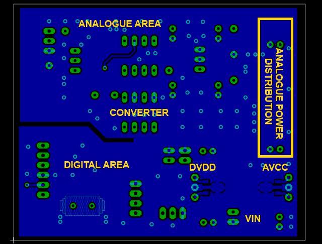
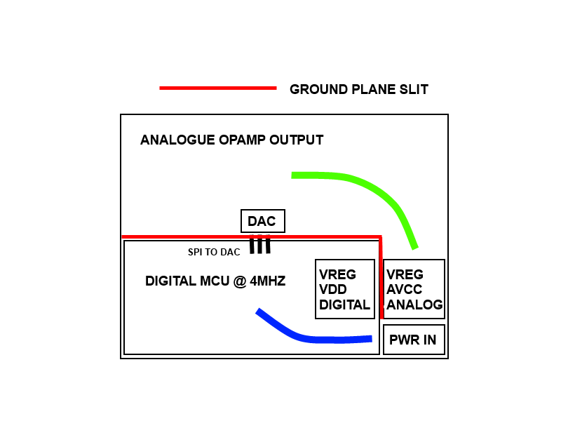
Is this a fair layout in terms of resolution? Green and blue are analogue/digital return paths respectively. As you can see, the input power is used for separate linear regulators, one for digital, and one for analogue. Only lines that cross the ground boundary are the SPI connections.
If I was to join the two ground planes under the DAC, surely the analogue return paths would have to go through the digital side?
Apologies for yet another 'layout' question. I realize each application is different, but there is much conflicting information floating around.
Scott