This thread has been locked.

If you have a related question, please click the "Ask a related question" button in the top right corner. The newly created question will be automatically linked to this question.

ADS1258EVM SPI Question

Other Parts Discussed in Thread: ADS1258

Hello,

I have a very strange experience with ADS1258. I can communicate with it when it is connected to the MMB0. In this config the MMB0 USB and Power supply inputs are not connected. I supply power to the EVM through J5A pins.

Here is my connection configuration:

J5.3 - 5V

J5.5 - GND

J5.9 - 3.3V

J5.6 - J6.4

---

J6.3 - SPI Clock

J6.4 - J5.6

J6.7 - SPI Chip Select (Device)

J6.8 (Clock Select) - J6.18

J6.11 - (Device MOSI)

J6.13 - (Device MISO)

J6.15 - Device Digital Input

No any other connection made.

In this case the MMB0 3 leds are on and more or less the communication is stable.

For communication I am using Pulse Convert command and polling the DRDY pin for going low then using the Register Data Read command the get the data. With this configuration I can successfully communicate with the ADS1258EVM. (SPI Clock rate is 1,2 MHz.) Sometimes the StatusByte.NewBit is not 1 - thats why I say more or less. I think its ok.

I wanted to remove the MMB0 and use only the EVM itself but somehow I SPI communication goes wrong. When I am trying to read the OFFSET value for example the StatusByte.ChannelID never returns the right ID. Lets call this error ChannelIDMissmatch. Well I decided to use a logic analyzer from SALEAE to see whats going on. 

And here is my experimental result:

Register Type: ADC.Registers.SysRed Value:   0x3D Default Value: 0x00
Register Type: ADC.Registers.MuxSg0 Value:   0x00 Default Value: 0xFF
Register Type: ADC.MuxSg1 Value:                      0x00 Default Value: 0xFF
Register Type: ADC.MuxDif Value:                        0x00 Default Value: 0x00

As you can see, the registers are configured to read only internal values.

Sending out the PulseConvertCommand:

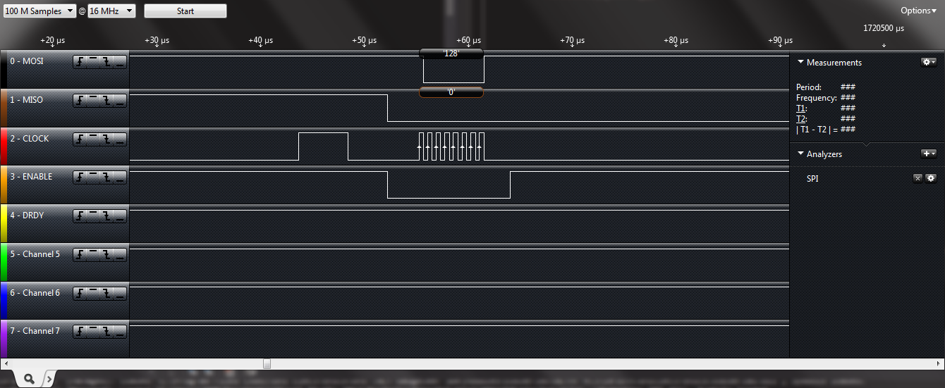
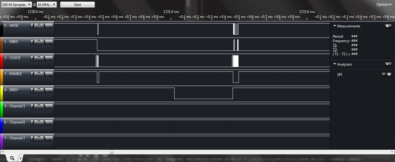
The entire communication: with DRDY

and Only the response with Wrong ChannelID Response:

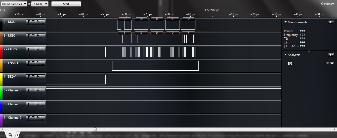
As you can see the '!' and Z indicates invalid data... 

I have reconnected the MMB0 and made another trial. Here is the result with the good outcome.

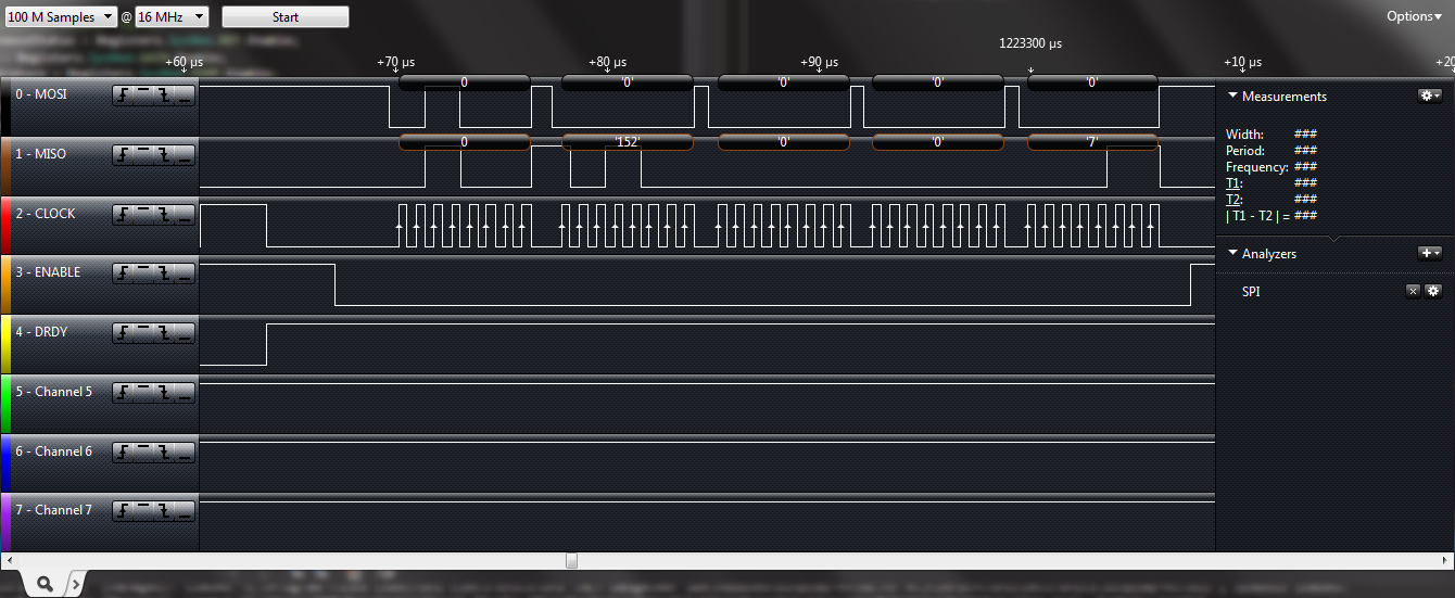
The value 152 equals to the value read from the ADS.

I am hoping someone can explain what is going on here :) and what should I do to use only the EVM.

Thank you in advance.

  • Hi Daniel,

    How do you have the jumpers set on J3 and J4?

    I recommend keeping them set to their default values, but adding a jumper to connect J4.13 and J4.14, so that the analog and digital grounds are properly referenced to each other.

    Your "J5.6 to J6.4" connection should being doing the same thing, but if it is a jumper wire, it will not be a short connection and could be disturbing your digital communication.

    If you still have communication issues, try probing the digital pins on the ADS1258 with and without the MMB0 to see if one of the signals (such as START) is changing states. The EVM should have pull-up and pull-down resistors to set all of these signals correctly; however, with the MMB0 connected (and un-powered) we cannot be sure of the state of those signals.

    Best Regards,
    Chris

    P.S. Feel free to post your Saleae logic file (with the data) to the E2E forums! I have the Logic software on my computer so I can open it up to look at closer.

  • Dear Chris,

    Thank you for your reply. I'm going to try this and come back with the result!

    Yes, I am using jumper wires and this could be an issue.Anyway what other wiring tools suggested for prototyping?

  • Hi Daniel,

    That is a good question!

    For prototyping you may have to use breadboards and jumper wire. It is important to be aware that for precision analog circuits or high-speed digital communication, the parasitic impedance introduced into your circuit (whether prototyping or the final PCB) can create problems such as distorting digital signals.

    The problem I think you are seeing is a large inductive impedance on the digital ground connection to the ADS1258. (While the Saleae is a nice tool, it doesn't show the whole picture. Try probing your digital signals with an oscilloscope and see how noisy they appear.)

    A PCB has the advantage that you can place a ground plane on the second layer (i.e. very close to the signal carrying trace). This keeps the loop area very small (that is the loop area of the signal and it's return current). Small loop area = small inductance (and less inductive noise coupling from nearby circuits). 

    If you ever use jumper wire to connect between two boards, try creating a twisted pair cable with the signal wire and a ground wire to keep the loop area small.

    Best Regards,
    Chris