This thread has been locked.

If you have a related question, please click the "Ask a related question" button in the top right corner. The newly created question will be automatically linked to this question.

ADS1278 AGND-DGND only 10 ohms, why?

Other Parts Discussed in Thread: ADS1278

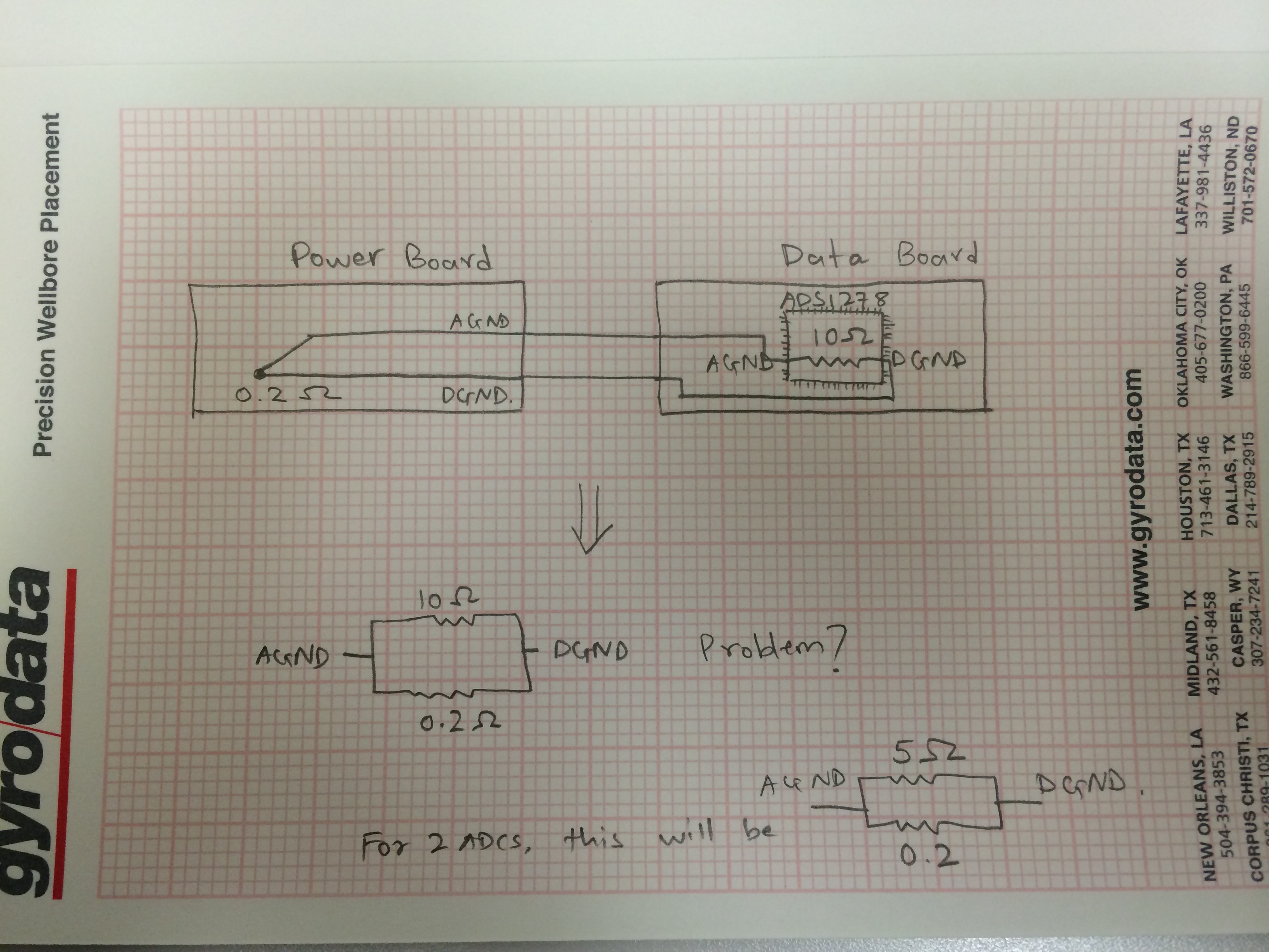
I had posted a question earlier about my concerns with the grounding on the ADS1278 chip. What I have found is that one of the designated AGND pins, 58 has a low impedance connection to the DGND pins 21,24,25. It measures out to be only 10ohms. Why would this be?

  • Hi Yashas, 

    As my colleague mentioned in the related post, there may be a low-impedance ESD diode path between AGND and DGND inside the device.

    More importantly, I think, is that you are connecting the two grounds together on a separate board. It is very possible that the trace impedance from AGND, through your power supply board, and back to DGND could sum up to 5-10 ohms.

    I do not think that what you are measuring is a sign of a problem (but it never hurts to be too careful :) ). Please make sure that you tie the two grounds to a common potential (i.e. 0 V) and keep the impedance low enough such that there is no more than 0.3 V between them.

    Best Regards,

  • Hi Ryan,

    The 10ohms I measured is on a free standing chip without any connections.

    Yes I have the AGND and DGND connection outside this board and so this 10 ohms is posing a problem in my system. I would like to have only one single AGND-DGND connection.

    Can I leave pin 58 open? I did get 0.5Mohms when I lifted pin 58 off its pad.

  • Hi Yashas, 

    Lifting pin 58 from the pad and leaving it disconnected is not the proper solution. In that configuration, I do not know what consequences it might have internally.

    I suggest carefully inspecting your layout and see where the 10 ohms may be coming from. On our ADS1278 EVM (daughter board only, J5 [5:6] not installed), I consistently measure 0.3-0.4 ohms between all AGND pins (6, 43, 54, 58, 59) and all DGND pins (7, 21, 24, 25).

    When you lifted pin 58 and measured 0.5 Mohms, were you probing the pin or the pad?

    Best Regards,

  • Hi Ryan,


    I am not sure if you read my reply earlier, so what I am trying to say is that the layout is not in question at all. Just take an ADS1278 chip from a reel/tray, no connections. Put it on your bench and ohm the pin 58 (AGND) and either of the pins 22, 24, 25 (DGND). You will see 10 ohms.


    I have a concern regarding this 10 ohms coming from the chip. Does it create a loop between AGND-DGND connections by the ADC (10 ohms) and the system where they are actually shorted (0.2ohms). Please see the attached file to get a better idea.

  • Hi Yashas, 

    Thank you for the diagram, this makes more sense to me now.

    I honestly do not know where the 10 Ohms is coming from, let me ask the designers if this is reasonable to expect. 

    Even with the 10 Ohms, the parallel combination of the two impedances is ~ 0.19 Ohms. This should be OK as long as the potential between AGND and DGND does not exceed +/- 300mV.

    I will get back to you next week with an update.

  • Hi Yashas,

    The impedance that you are measuring between AGND and DGND may exist because back-to-back diodes were placed in between to tie them together. If you are measuring with a multi-meter, you should see a different impedance between the two pins when you reverse the Red and Black leads. Basically, this means that the low impedance you measured is expected as part of the chip design and cannot be avoided. Do not lift the pins off of the PCB.

    That said, you are correct that having internal and external connections between AGND and DGND will form a ground loop, which best practices generally tell us to avoid. The best we can do is to externally short AGND and DGND directly beneath or close to the device. Then, you can mitigate the effect of the ground loop by only bringing one connection from the Data Board over to your Power Board (use the AGND connection). The thermal pad on the ADS1278 should also be tied to AGND.

    Let me know if this makes sense. 

    Best Regards,

  • Hi Ryan,

    Ok that info. is good. Thanks for the update.

    This needs to be on the datasheet!

    Regards,

    Yashas