This thread has been locked.

If you have a related question, please click the "Ask a related question" button in the top right corner. The newly created question will be automatically linked to this question.

ADS1258 blocked

Other Parts Discussed in Thread: ADS1258

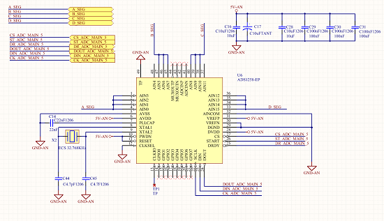
Hi all, I have some problems with the ADS1258 24 bit ADC. The ADC don't give out the PLL clock from CLKIO and don't  run the SPI communication line.

My doubts are:

- I use the same power line for analog and digital section (5V from LDO)

- I anchored the reset line and the powerdown line (datasheet allows the reset of device by SPI command)

may be the reasons of adc problems?

if you have suggestions I would appreciate it!!

thank you so much

Claudio

  • Hi Claudio,

    Welcome to the TI E2E Forum!

    Your schematic configurations look correct. If you are not getting the clock output then I would probe your 32.768 kHz crystal to make sure it is starting up. (Some crystals require more drive power than others and ADC's are usually designed for lower power consumption and do not spare much current for driving the crystal. Crystals can also be sensitive to layout and parasitic capacitance in your circuit.)

    Other things that would cause no clock output would be putting the ADS1258 in power down mode, changing the CLKENB bit in the ADS1258 CONFIG0 device register, or pulling CLKSEL high. It is not likely that these are problems in your circuit since you have tied the digital pins to the correct logic levels and by default the ADS1258 is configured to output the clock.

    Regarding your concerns:

    CLAUDIO BIANCHI said:
    I use the same power line for analog and digital section (5V from LDO)

    This is okay as long as you place separate decoupling capacitors close to each supply input (AVDD and DVDD).

    CLAUDIO BIANCHI said:
    I anchored the reset line and the powerdown line (datasheet allows the reset of device by SPI command)

    No problem here!

    Best Regards,
    Chris

  • Hi Chris,

    thank you for the answer!! yes che crystal is start up give us the right frequency !!! The crystal used is the MC-306 32.7680K-A0 (the same reported on datasheet) with the 4.7pf capacitors.

    the spi fuctions are correlated with the adc internal clock or the spi  interface  not depending from internal master clock ??

    What are the SPI configurations suggested ??? SPI Clock frequency, clock polarity and fase, MSB first or not ??

    thank you so much

    best regards,

    Claudio

  • Hi Claudio,

    If the crystal is working and you still do not see the clock output, then you likely have a bad connection (something that does not match up with your schematic) or perhaps the ADS1258 may have sustained ESD damage during handling.

    Try probing around the ADS1258. Check for a solder-bridge short between pins or between a pins and the thermal pad. You can request additional free samples of ADS1258 devices here: http://www.ti.com/product/ADS1258/samplebuy


    CLAUDIO BIANCHI said:
    the spi fuctions are correlated with the adc internal clock or the spi  interface  not depending from internal master clock ??

    SPI communication uses the SCLK to decode commands.The SCLK and internal ADC clock do not need to be synchronous.

    Internally the system clock uses the 32.768 kHz crystal and PLL to generate a 15.729 MHz clock. SCLK must be 1/2 the system clock frequency (7.8645 MHz or less).


    CLAUDIO BIANCHI said:
    What are the SPI configurations suggested ??? SPI Clock frequency, clock polarity and fase, MSB first or not ??

    The suggested settings will depend on which inputs and features you want to use. By default the ADS1258 will operate in auto-scan mode and will multiplex through all 16 single-ended inputs.


    Best Regards,
    Chris

  • Hi Chris, an other thank you for the answer. I bought the evaluetion board to validate my software. next step I will redefine the layout of PCB.

    I exclude the ESD damage, we work in ESD workstation inside the cleaning room. I mounted two ADC and both are blocked. I have tried to replace one of them but non news for me.

    I checked (1000 time) the schematic and I checked if are presents solder-bridges.

    I followed your advice ordering two sample and then I will remake the PCB like the evaluetion boad  and will try again to "play" with the ADC.

    Best regards

    Claudio