This thread has been locked.

If you have a related question, please click the "Ask a related question" button in the top right corner. The newly created question will be automatically linked to this question.

ADS1298: problem with some channels test signal and all channels with external signal

Other Parts Discussed in Thread: ADS1298

Hi,

I'm working on a project with the ADS1298 (custom board) using one Freescale Kinetis K10 to read the signal and store it into a uSD card. At this moment I'm able to write and read all registers, change sampling frequency (checked by oscilloscope with DRDY line) and read data. I'm using continuous mode to read the data.

Problems I'm facing:

1.   I can't get external signal form any channel.

2.   When I set all channels into test signal (using internal signal generation), I can get the test signal in channels 4,5,7,8 only. From channels 1,2,3 and 6 I only get some DC level with some small noise.

3. Lead status never change (external signal nor calibration signal). They all come in '0' regardless their actual connection status.

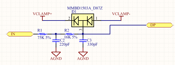
This is my circuit: I changed the channels order to read them back already ordered. I checked the datasheet many time before doing this and I didn't see any reason to input V6 in IN1P. 

The channels input is as follows:

My registers initialization for internal test signal are:

0x06,   //0x42, //CONFIG1 
0x30,   //CONFIG2
0xDC,  //0xCE, //CONFIG3 2.4Vref
0x13,   // LOFF by pull-up/down
0x65,   //CH1SET
0x65,   //CH2SET
0x65,   //CH3SET
0x65,   //CH4SET
0x65,   //CH5SET
0x65,   //CH6SET
0x65,   //CH7SET
0x65,   //CH8SET
0x07,   //RLDSENSP (default)
0x07,   //RLDSENSM (default)
0xFF,   //LOFF_SENSP
0xff,      //0x02,//LOFF_SENSM
0x00,   //LOFF_FLIP (default)
0x00,   //LOFF_STATP (Read only)
0x03,   //LOFF_STATM (Read only)
0xe1,   //GPIO Input only PACE_OUT (coming from external pacemaker detector)
0x01,   //PACE (default) // PaceBuffer ON (TODO: Make this contitional according to the pacemaker setting)
0x00,   //RESP (default)
0x02,   //CONFIG4  Leadoff comparators ON
0x09,   //0x08, //WCT1
0xc2,   //0xCB, //WCT2

I'm starting to think that the chip is somehow broken but I'm afraid to replace it and still have the same problem. I only have one prototype at this moment.

Please let me know if you find some problem in the circuit diagram or register initialization (I changed the registers to almost very possible settings always keeping 2.4V reference).

If you need more information, just let me know.

Thank you for your support.

William

  • Hi William,

    Thanks for your post! Here are my initial thoughts:

    1. I noticed that the PACE register is set to 0x01. Setting Bit 0 to '1' will enable the internal PACE amplifiers, which drive the same pins that the internal test signal would be driven to (TESTP_PACE_OUT1 and TESTN_PACE_OUT2). You will want to change that bit to '0' to power down these amplifiers in order to measure the internal test signal at these pins.
    2. Using the internal test signal and the internal reference, I do not see a reason why some channels would work and others would not. Does the issue always occur in the same channels? Please do a register read to confirm that the settings were written properly. If you still see an issue, would you mind sharing a scope capture showing all 8 channels?
    3. I do not believe that the lead-off detection circuitry is connected to the channel inputs when the channels are configured to use the internal test signal (but I'll have to check this). Does lead-off detection work when you change the channels to Normal Electrode?

    Best Regards,

  • Hi Ryan Andrews,

    Thank you very much for your help, I set the PACE bit to '0' but problem was still there. after that I checked the board assembly one more time and found what I think the problem was:

    Short circuit between IN3P and IN3N. I was getting test signal in channels 4,5,7 and 8.

    The problem with no getting external signal was caused by I was using, some how it has the chassis connected to N (RF) and I had my AGND connected to patient cable shield too. This might be affecting something. I removed the connection between AGND and the patient cable shield and it started working as expected.

    About the leadoff detection problem, I had the threshold  to the maximum. I changed it to the lowest value and most of them start operating normally. I will recheck the soldering today, maybe I will find the cause of the problem there.

    Finally my register are like this:

    0x06, //CONFIG1
    0x10, //CONFIG2
    0xCC, //CONFIG3 2.4Vref
    0xf3, // LOFF by pull-up/down
    0x00, //CH1SET
    0x00, //CH2SET
    0x00, //CH3SET
    0x00, //CH4SET
    0x00, //CH5SET
    0x00, //CH6SET
    0x00, //CH7SET
    0x00, //CH8SET
    0x03, //RLDSENSP
    0x01, //RLDSENSM
    0xFF, //LOFF_SENSP
    0xff, //LOFF_SENSM
    0x00, //LOFF_FLIP (default)
    0x00, //LOFF_STATP (Read only)
    0x03, //LOFF_STATM (Read only)
    0xe1, //GPIO Input only PACE_OUT (coming from external pacemaker detector)
    0x00, //0 for test signal 0x01, //PACE PaceBuffer ON (TODO: Make this contitional according to the pacemaker setting)
    0x00, //RESP (default)
    0x02, //CONFIG4 Leadoff comparators ON
    0x09, //WCT1
    0xc2, //WCT2

    Thank you again for your support.

    Best regards,

    William

  • Hi William,

    I'm glad that you found the cause of the issue. Let us know if you run into further trouble.

    Best Regards,