This thread has been locked.

If you have a related question, please click the "Ask a related question" button in the top right corner. The newly created question will be automatically linked to this question.

ADS1120 differential input current

Other Parts Discussed in Thread: ADS1120

Hi,

I got some questions about ADS1120 characteristics as follows,

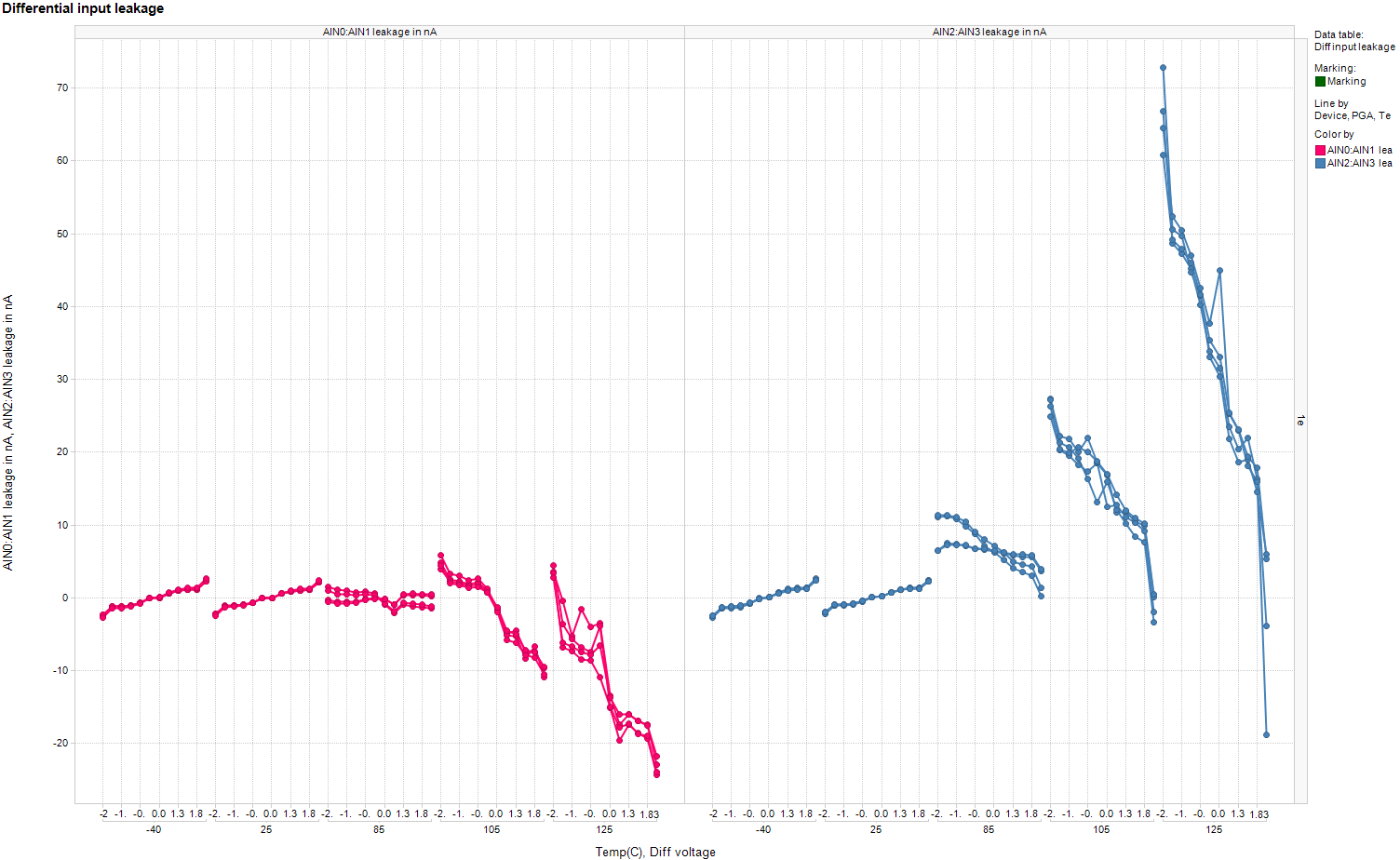
1. My customer needs the maximum value of differential input current of ADS1120.

They had adjusted manually by 1 piece before.

Now, it is hard because of increasing production.

So, they need to know the maximum value of differential input current.

Could you show me the reference maximum value or dispersion map?

The following are is operating condition.

AVDD = REFP = 4.02V
AVSS = REFN = 0V(AGND)
DVDD = 3.3V.

GAIN =128V/V

2. Seen in the Figure 16~19. Input current vs Input voltage,

   Could you tell me that why Input current of AIN2 and AIN3 are large?

   I seem that all input terminal are same on block diagram.

 Thanks,

Kuramochi

  • Hi Kuramochi-san,

    The differential currents follow the graph given in the datasheet.  I've included the collected data graph below.  This is not a guaranteed specification so we really don't have minimum or maximum values as the current is not tested at final test. 

    The bulk of this current comes from leakage.  Some of this is through the ESD cells.  For AIN3, in particular, the additional leakage is related to the low-side switch.  The current increases primarily at around 85 deg C or greater, otherwise it stays fairly uniform.

    Best regards,

    Bob B

  • Bob-san,

    Thank you for your reply and showing the data.

    I'm sorry that the explanation is lack.

    Do you have the dispersion map @25℃ in a wafer?

    My customer needs the maximum value @25℃.


    I understood the bulk of this current.

    Thanks and Regards,

    Kuramochi

  • Hi Kuramochi-san,

    Unfortunately this is not a parameter that was studied in normal characterization so I do not have any data to show you as to how much this differential current can change from device to device, or from lot to lot. One of the reasons we did not collect a lot of data for the differential current is because we saw very little change in the absolute current of a number of devices at 25 deg C over the input range, so there was really no need to analyze the differential current further.  From figure 15 of the ADS1120 datasheet you can see that the absolute input current tracks very nicely from input to input at 25 deg C.

    At 25 deg C, figures 18 and 19 show nearly flat response and very little to no difference when comparing the 2 differential input pairs.  What we are attempting to show in these figures is that with increased operating temperature there is an increase in leakage current.  In normal operation at 25 deg C the current is primarily input bias current induced in the chopper input stage of the input amplifier.

    Best regards,

    Bob B

  • Hi Bob-san,

    After all, the input current is important for my customer.

    They can't use ADS1120 as long as they don't know the max input current.

    Could you please examine it?

    Thanks and Regards,

    Kuramochi

  • Hi Kuramochi-san,

    The graph I sent previously is the only data we have for differential current.  At 25 deg C the distribution is very close for the four devices tested.  On the graph it appears as only one device is plotted, but it is all four.  The difference from device to device is around 200pA across the devices at a particular voltage input.  I can average those numbers for those devices, but there is no guarantee that another set of devices will be the same as we do not measure this in final test as the currents are not a guaranteed specification.  Across the input range the differential current is about +/-2.5nA.

    Best regards,

    Bob B

  • Dear Kuramochi-san,

    I am the product definer of the ADS1120.
    As Bob already said, we don't have sufficient characterization data available for the ADS1120 and we also do not test the differential input current at final test. Therefore we cannot guarantee a maximum differential input current, even if it is only at 25°C.

    The current also depends a lot on the common-mode voltage of the signal and on the signal levels of the currently not selected inputs. This all makes specifying it really difficult.

    What would be a maximum current your customer could accept?

    Regards,

  • Joachim-san,

    Bob-san,

    Thank you for your information.

    Now, I'm negotiating with my customer.

    ******************************

    I have an another question.

    My customer use ADS1120 at 40℃(max)

    Could you show me the data of Differential Input Current at 40℃?

    If there is no data, do you have the data as we can suppose the characteristic at 40℃?

    Best Regards,

    Kuramochi

  • Hi Kuramochi-san,

    we did unfortunately only measure the input currents at 25°C and 85°C. However at 40°C I don't expect a lot of change compared to the 25°C data.
    I would tell your customer that the data that we show above and in the datasheet at 25°C is more or less valid at 40°C as well.

    Regards,

  • Joachim-san,

    Thank you for your reply.

    You don't have the data of  "Differential Input Current vs Temparature" , do you?

    And, how many degrees is it that the input current begins to increase sharply?  

    Regards,

    Kuramochi 

  • Hi Kuramochi-san,

    the plots that Bob posted above show the differential input current of four different devices over temperature.
    At 25°C you cannot see any difference between the four devices as the values are very similar (in the single digit nA range or less). At the higher temperatures you see some differences between the devices.
    This is all data we have.

    If you need to tell your customer a number, I would say a maximum differential input current of +/-10nA over the temperature range from 25°C to 40°C should be a realistic number. But we don't guarantee that in any form.

    Regards,

  • Hi, Joachim-san,

    Thank you for your quick reply.

    I understood that the plot above is all data you have.

    So, you don't know that how many degrees is it that the input current begins to increase sharply, do you?

    Best Regards,

    Kuramochi

  • Hi Kuramochi-san,

    unfortunately not. We typically run all our detailed characterizations at those certain temperatures only (-40°C, 25°C, 85°C, 105°C, 125°C).
    The values usually start to become worse between 60°C to 85°C. At 40°C I would really not expect a lot of change in performance.

    Regards,

  • Hi Joachim-san,

    Thank you for your reply.

    I tell your information to my customer.

    Thanks and Regards,

    Kuramochi