This thread has been locked.

If you have a related question, please click the "Ask a related question" button in the top right corner. The newly created question will be automatically linked to this question.

SPI Data Mode for AFE4490

Other Parts Discussed in Thread: AFE4490

This might be an easy question, but I'm new to these things, so I wanted to ask to be sure. I'm using an Arduino board that uses the ATmega328 8-bit MCU.

On the FAQ thread, it says "The MCU serial port must be configured to latch serial data out on falling edge, such that AFE44xx can clock data in on the rising edge.  Likewise, the AFE44xx will shift data out on the falling edge so MCU can clock data in on the rising edge."

Which one of these modes is appropriate for the AFE4490? This is from the ATmega328 datasheet.


Thanks!

  • Mohammad,

    SPI mode 0 should work.

  • Thanks for the verification on that. I'm currently trying to debug some SPI communication issues. Would be so kind to tell me if the read and write functions I am using below look correct?

    void RegisterWrite (uint8_t address, uint32_t data)
    {
        digitalWrite (SPISTE, LOW); // enables device
        SPI.transfer (address); //sends register address
        SPI.transfer ((data >> 16) & 0xFF); // top 8 bits
        SPI.transfer ((data >> 8) & 0xFF); //middle 8 bits
        SPI.transfer (data & 0xFF); //bottom 8 bits    
        digitalWrite (SPISTE, HIGH); // disables device
    }

    uint32_t RegisterRead (uint8_t address)
    {       
        uint32_t data=0;
        digitalWrite (SPISTE, LOW); // enables device
        SPI.transfer (address); // sends register address
        data |= (SPI.transfer (0)<<16); // reading the top 8 bits of data
        data |= (SPI.transfer (0)<<8); // reading the middle 8 bits of data
        data |= SPI.transfer (0); // reading the bottom 8 bits of data
        digitalWrite (SPISTE, HIGH); // disables device
        return data; // return the read 24 bits of data
    }

    SPI.transfer and digitalWrite are from the Arduino library.

    http://arduino.cc/en/Reference/SPITransfer

    http://arduino.cc/en/Reference/digitalWrite

  • The code snippet you provided seems valid.

    Can you post your AFE4490 driver code API for the Arduino Platform?

  • Hi Praveen,

    I'm still working on the driver code. I was testing to see if I could read and write to the registers using the above functions and wanted to double check. The good news is that I am able to get the LEDs on the DCM03 to light up so far!

  • Ok, I'm simply trying to write to some registers and read the values back. Here's my result. Any ideas why the register values are read incorrectly?


    void setup() is only run once. void loop() runs repeatedly and produces the console output shown.

    Btw, the LEDs do not light up.

    Code Below

    #include <intrinsics.h>
    #include <string.h>
    #include <SPI.h>
    #include "AFE4490.h"

    const int SCLK = 13;
    const int SOMI = 12;
    const int SIMO = 11;
    const int SPISTE = 10;
    const int ADC_RDY = 9;

    void AFE4490Initialize (void);
    void RegisterWrite (uint8_t address, uint32_t data);
    uint32_t RegisterRead (uint8_t address);

    void setup()
    {
       Serial.begin(9600);
        
       SPI.begin();
       pinMode (SOMI, INPUT);
       pinMode (SPISTE, OUTPUT);
       pinMode (SCLK, OUTPUT);
       pinMode (SIMO, OUTPUT);
       pinMode (ADC_RDY, INPUT);
       
       SPI.setClockDivider (SPI_CLOCK_DIV128); //Divides 8 MHZ clock by 128 = 62.5 KHz
       SPI.setDataMode (SPI_MODE0);
       SPI.setBitOrder (MSBFIRST);
     
       AFE4490Initialize(); //Function used for initializing the AFE4490
       
    }

    void loop()
    {
      RegisterWrite(CONTROL0, 0x000001); //SPI_Read Enable
      Serial.println(RegisterRead(LEDCNTRL), HEX);
      Serial.println(RegisterRead(TIAGAIN), HEX);
      Serial.println(RegisterRead(TIA_AMB_GAIN), HEX);
      Serial.println("\n");
      delay(1000);
    }

    ////////////////////Functions Below/////////////////////////

    void AFE4490Initialize (void)
    {
        Serial.println("Initializing \n");
        RegisterWrite(CONTROL0, 0x000008); //SW_RST
        RegisterWrite(LEDCNTRL, 0x11414);
        RegisterWrite(TIAGAIN,0x008002);
        RegisterWrite(TIA_AMB_GAIN,0x004404);
        Serial.println("Initialization Complete. \n");
    }

    void RegisterWrite(uint8_t address, uint32_t data)
    {
        digitalWrite (SPISTE, LOW); // enable device
        SPI.transfer (address); // send address to device
        SPI.transfer ((data >> 16) & 0xFF); // writing top 8 bits
        SPI.transfer ((data >> 8) & 0xFF); // writing middle 8 bits
        SPI.transfer (data & 0xFF); // writing bottom 8 bits    
        digitalWrite (SPISTE, HIGH); // disables device
    }

    uint32_t RegisterRead(uint8_t address)
    {       
        uint32_t data=0;
        digitalWrite (SPISTE, LOW); // enables device
        SPI.transfer (address); // sends address to device
        data |= (SPI.transfer (0)<<16); // reading top 8 bits data
        data |= (SPI.transfer (0)<<8); // reading middle 8 bits  data
        data |= SPI.transfer (0); // reading bottom 8 bits data
        digitalWrite (SPISTE, HIGH); // disables device
        return data; // returns with 24 bits of read data
    }

    Console Output Below

    Initializing

    Initialization Complete.

    1414
    FFFF8002
    4404


    1414
    FFFF8002
    4404


    1414
    FFFF8002
    4404


    Thanks!

  • Any help or suggestions on this issue? thanks.

  • Mohammad,

    Clearly 16 bits (lower 2 bytes) are being written and read correctly.

    When register reads returns unsigned 32-bit data with MSB = 0, then where does the MSB 'FF' in "FFFF8002" come from?

    Can you check the size of uint32_t? It seems like it is type defined to 16-bits.

    Also capture the SPI waveforms on the oscilloscope and check if the SPI writes and reads are as expected.

  • Hello Praveen,


    Thanks for your response.

    sizeof(uint32_t)=4


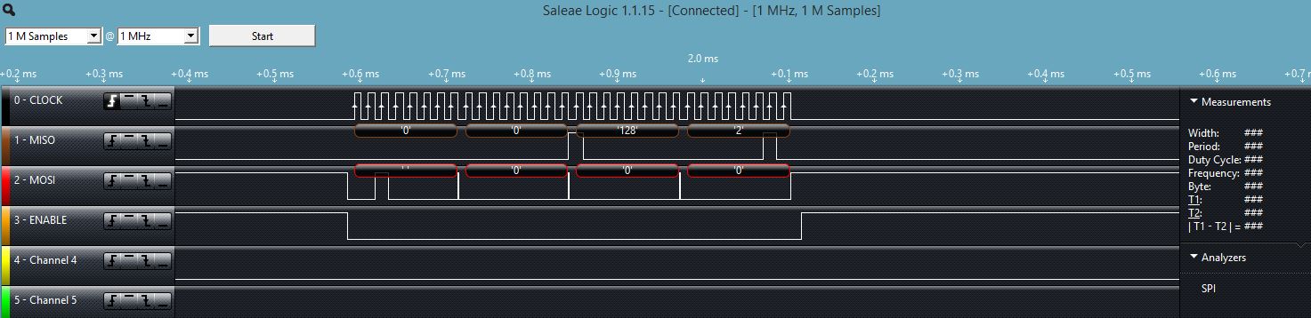
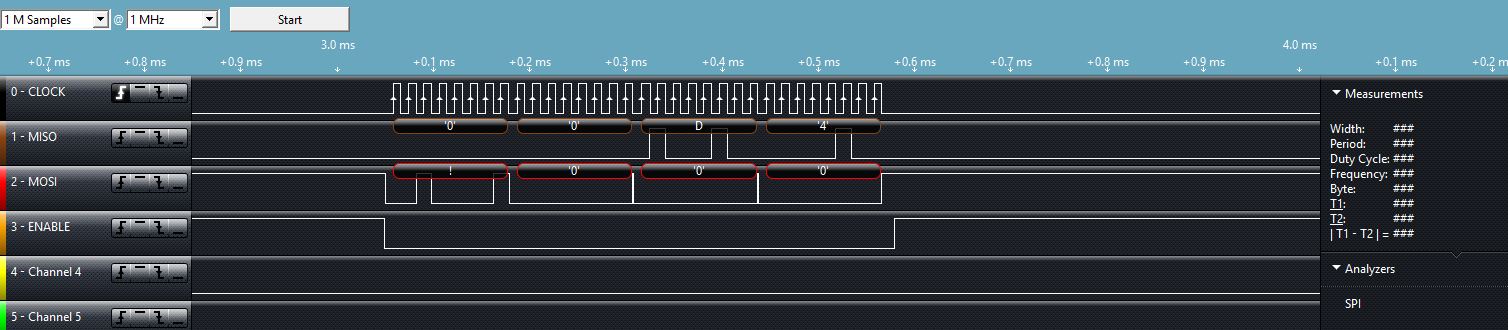
    Also, here are some screen caps of the output of my usb logic analyzer. I set the trigger on the rising edge of the clock.

  • Hello Mohammad,

    Pleas let me know if you were able to resolve this issue.

    Regards.

    Praveen.

  • Hi Praveen,


    Yes, it seems like I resolved it. For reading the registers properly, I had to send an additional dummy byte first in order to get the full 24 bits in return. I also ended up using the 'long' dataype instead.

    Thanks.

  • Mohammad,

    Good to know that you have resolved it.

    If you have made the driver code working, please publish the basic driver code and its related documentation in the forum so that it will be useful to other community users who are also using the AFE44xx with the Arduino platform.


    Best Regards.