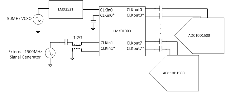
I want to use a LMK01000 clock buffer in the clock generation because I want to place more than one ADC10D1500 in this board and I would like to clarify some questions about the LMX2531-LMK01000-ADC10D1500 connection.
In am using as reference the design in ADC10D1x00RB board but I need to place a LMK01000 between the LMX2531 and the ADCs. I want to keep the possiblity to choose between the LMX2531 output and an external clock. I could use the LMK01000 for this since it has two clock inputs but I rather use a control signal as it is in the ADC10D1x00RB design than programming the registers in LMK01000 to choose the clock. So that I have placed a relay to choose the input clock. In ADC10D1x00RB board the output of the relay is connected to a transformer in order to generate a differencial clock and then this differencial clock goes to the ADC.
Since the LMK01000 allows the use of either single ended of differencial clock inputs I can skip the use of the transformer and connect the single ended output of the relay directly (through a decoupling capacitor) to one of the inputs of the LMK01000 and connect the complementary input of that clock to GND (AC ground as it is specified in the datasheet). Is this OK? Is there any advantage in using a differential clock as input for the LMK01000?
After that, the differential outputs of the LMK01000 can be directly connected to the ADC clock inputs by using just decoupling capacitors in series (AC coupling is a must for ADC10D1500). I mean, I do not need any 100 Ohm resistor since the CLK+/- pins in the ADC10D1500 have them internally. Am I right?
For the uWire communication with LMX2531 and LMK1000, I will use the scheme depicted Figure 2 in the LMK01000 datasheet. Since all the pins are inputs and are 1.8V operation compatible, I will use a microcontroller supplied at 1.8V. I guess there is no risk for the IO pins of the microcontroller (no 3-3.3V signals expected at these pins).
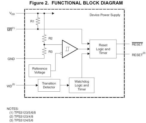
And finally, a simple question about the power supply. If I want to generate a signal to monitorize the voltage supply of the ADC, could you recommend me a chip (a kind of power on reset) to be used to monitorize this 1.9V supply?