This thread has been locked.

If you have a related question, please click the "Ask a related question" button in the top right corner. The newly created question will be automatically linked to this question.

ADS1299 get device id though spi

Other Parts Discussed in Thread: ADS1299, ADS1256

Hi,

I am currently using the ADS1299 with the Beagleboard Black. I am not very familiar with SPI communication. That' s why I am trying to begin with easy stuff like just read the device id of the ads1299 with the BB.

My current wiring in the ads1299 side is :

  • CS0 -> pin 39
  • Doutput -> pin 43
  • Dinput -> pin 34
  • SCLK -> pin 40
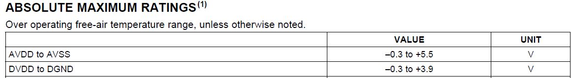
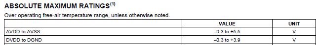
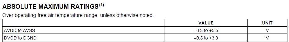
  • AVDD -> pin 56 (+5V)
  • AVSS -> pin 57 (-5V)
  • DVDD -> pin 50 (+3.3V)
  • DGND -> pin 49 (-3.3V)

I wrote my own piece of code in C using spidev to read device id but I was only able to read FF in the answer from ADS1299. My current process is to send SDATAC,then RESET then use the RREG command on the first register to try to get device register id. Because I am not able to understand if it is a software or wiring issue, I also tried with a piece of code find on this forum on this post : http://e2e.ti.com/support/data_converters/precision_data_converters/f/73/t/351973.aspx

After some modification to fetch ads1299 instead of ads1256 and my current need, the code is :

int spi_init (int *fd, uint8_t *mode, uint8_t *bits, uint32_t *speed, char *device)
{
  int ret=0;

  //Open device
  (*fd) = open(device, O_RDWR);
  if (fd < 0)
    return -1;

  //SPI Mode
  ret = ioctl((*fd), SPI_IOC_WR_MODE, mode);
  if (ret == -1)
    return -2;

  ret = ioctl((*fd), SPI_IOC_RD_MODE, mode);
  if (ret == -1)
    return -3;

  //Bits per word
  ret = ioctl((*fd), SPI_IOC_WR_BITS_PER_WORD, bits);
  if (ret == -1)
    return -4;
  ret = ioctl((*fd), SPI_IOC_RD_BITS_PER_WORD, bits);
  if (ret == -1)
    return -5;

  //Max speed in Hz
  ret = ioctl((*fd), SPI_IOC_WR_MAX_SPEED_HZ, speed);
  if (ret == -1)
    return -6;

  ret = ioctl((*fd), SPI_IOC_RD_MAX_SPEED_HZ, speed);
  if (ret == -1)
    return -7;
  return 0;
}


int main (int argc, char *argv[])
{
  int fd,opt,ret=0,res=0;
  char device[MAX_BUF]="/dev/spidev1.0";
  uint32_t speed=1000000, dummy;
  uint8_t mode=1, bits=8, spiregister[10],spivalue[2],rx[ARRAY_SIZE(spiregister)] = {0,0,0,0,0};
  unsigned short int delay =10;
  unsigned char repeated_iteration = 0;


  struct spi_ioc_transfer tr = {
    .tx_buf = (unsigned long)spiregister,
    .rx_buf = (unsigned long)rx,
    .len = ARRAY_SIZE(spiregister),
    .delay_usecs = delay,
    .speed_hz = speed,
    .bits_per_word = bits,
  };

  //Init_SPI
  res=spi_init(&fd, &mode, &bits, &speed, device);

  if (res==-1)
    pabort("can't open device");

  if (res==-2)
    pabort("WRITE: can't set spi mode");

  if (res==-3)
    pabort("READ: can't get spi mode");

  if (res==-4)
    pabort("WRITE: can't set bits per word");

  if (res==-5)
    pabort("READ: can't get bits per word");

  if (res==-6)
    pabort("WRITE: can't set max speed hz");

  if (res==-7)
    pabort("READ: can't get max speed hz");

  //Show SPI Information

  printf("spi mode: %d\n", mode);
  printf("bits per word: %d\n", bits);
  printf("max speed: %d Hz (%d KHz)\n", speed, speed/1000);
  printf("spidev node: %s\n", device);
  deg("TI-ADS1299 Configuring\n");

  spiregister[0] = 0x11;                //SDATAC Command
  ret = ioctl(fd, SPI_IOC_MESSAGE(1), &tr);
  if (ret < 1)
    pabort("Config : can't send spi message");
  usleep(100);

  /****** RESET ******/
  spiregister[0] = 0x06;                //RESET Command
  ret = ioctl(fd, SPI_IOC_MESSAGE(1), &tr);
  if (ret < 1)
    pabort("Config : can't send spi message");
  usleep(100);


  deg("Reading the Value\n\n\n");
  int data;

  while(1)
  {
    spiregister[0] = 0x20;            //RDATA
    ret = ioctl(fd, SPI_IOC_MESSAGE(1), &tr);
    if (ret < 1)
      pabort("Config : can't send spi message");
    sleep(1);


    printf("MSB = %.2X\n",rx[1]);
    data = rx[1];
    printf("DATA = %.2X\n",rx[2]);
    data = (data << 8) | rx[2];
    printf("LSB = %.2X\n",rx[3]);
    data = (data << 8) | rx[3];
  }

  close(fd);
  return 0;
}

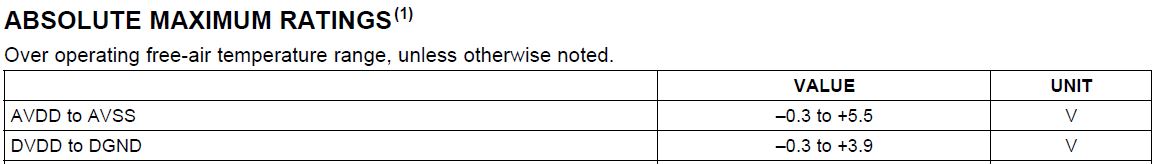
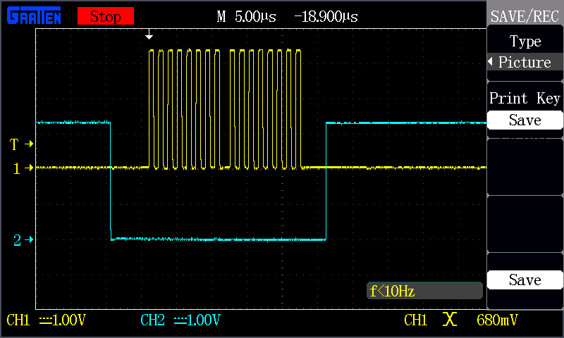
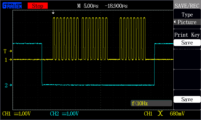
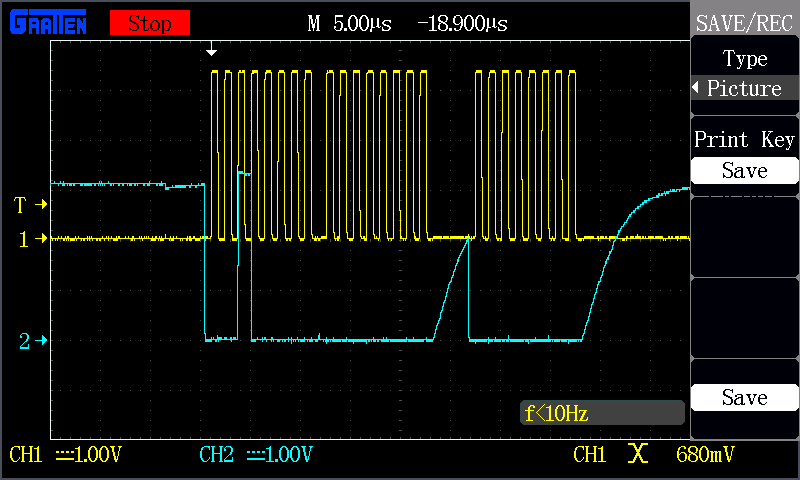
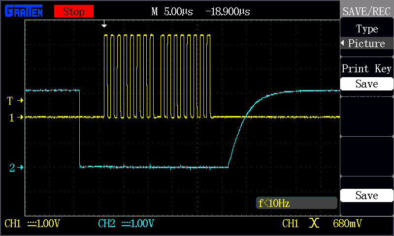
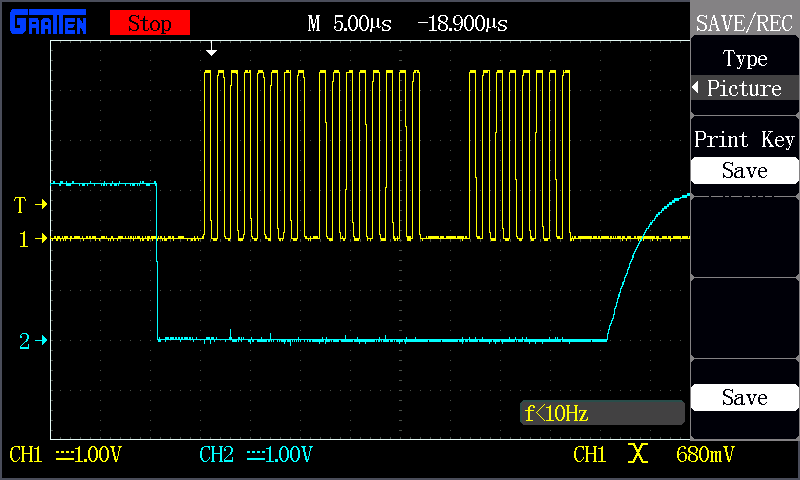
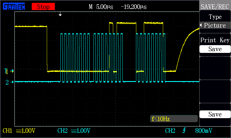
I am only able to read FF in the answer again.... Is there any issue in my current wiring or code ?

Thanks & Regards,

Arthur.

  • **TI EDIT February 20th 2019; FOR GENERAL ADS129x ASSISTANCE, PLEASE SEE NEW BIOPOTENTIAL FAQ LOCATED HERE**

    Hi Arthur,

    Sorry for the delay in my reply. Have you managed to resolve the SPI communication issue?

    I saw on another thread that you were seeking help from our BeagleBoard team and asked whether the SCLK should be an input or output. To the ADS1299, the SCLK is an input, so it would be an output from your processor. :)

    If you have any other questions related to the ADS1299, I would be glad to help you here.

    Best Regards,

  • Hi Ryan,

    Thanks you for your answer about the SLCK. I was able to check that it is correct thanks to an oscilloscope. I am always failing to get data from ads1299. I check the CS, command sent and SLCK output on oscilloscope and all seems to be ok.

    I can see that ads1299 never answer at all. I have two ADS1299 and the result is the same.

    In my opinion my issue can be due to three points :

    • Code
    • Defective wire
    • Error in device tree file

    I am currently trying to exclude one of these to reduce the possibilities...

    Best Regards,

    Arthur.

  • Hi again Ryan,

    I have run again some test today with two differents ads1299 and always strange result. I am able to read value different from 0x0 in the rx buffer but value are not good. Moreover I can see that the value is increasing when I call again my program.

    I was able to check thanks to my oscilloscope that all my wire are ok. I am able to see the same signal on my Beaglebone Black and on the pin of the ADS1299.

    I have clearly a big mistake somewhere but I am not able to see it. 

    My device tree file on the BB :

    /dts-v1/;
    /plugin/;
    
    / {
        compatible = "ti,beaglebone", "ti,beaglebone-black";
    
        /* identification */
        part-number = "spi0pinmux";
    
        exclusive-use =
        		  /* the pin header uses */
    		  "P9.17", /* CS */
    		  "P9.18", /* DI */
    		  "P9.21", /* D0 */
    		  "P9.22"; /* SCLK */
    
        fragment@0 {
            target = <&am33xx_pinmux>;
            __overlay__ {
                spi0_pins_s0: spi0_pins_s0 {
                    pinctrl-single,pins = <
                      0x15c 0x10  /* spi0_cs0, OUTPUT_PULLUP | MODE0 */
                      0x158 0x10  /* spi0_d1, OUTPUT_PULLUP | MODE0 */
                      0x154 0x30  /* spi0_d0, INPUT_PULLUP | MODE0 */
                      0x150 0x10  /* spi0_sclk, OUTPUT_PULLUP | MODE0 */
                    >;
                };
            };
        };
    
        fragment@1 {
            target = <&spi0>;
            __overlay__ {
                 #address-cells = <1>;
                 #size-cells = <0>;
    
                 status = "okay";
                 pinctrl-names = "default";
                 pinctrl-0 = <&spi0_pins_s0>;
    	     /*ti,spi-num-cs = <0x2>;*/
    	     /*interrupts = <0x65>;*/
                 spidev@0 {
                     spi-max-frequency = <1000000>;
                     reg = <0>;
                     compatible = "spidev";
                 };
            };
        };
    };
    

    Source code used to send RREG command to get device id :

    #include "ads1299_spi.h"
    
    #define ARRAY_SIZE(a) (sizeof(a) / sizeof((a)[0]))
    #define MAX_BUF 64
    
    int spi_init ()
    {
      int ret=0;
      int lsb = 0;
      int mode = SPI_MODE_1;
      int speed = 1000000;
      int bits = 8;
      int fd;
    
      //Open device
      fd = open("/dev/spidev1.0", O_RDWR);
      if (fd < 0)
        return -1;
    
      //SPI Mode
      ret = ioctl(fd, SPI_IOC_WR_MODE, &mode);
      if (ret == -1)
        return -1;
    
      ret = ioctl(fd, SPI_IOC_RD_MODE, &mode);
      if (ret == -1)
        return -1;
    
      //Bits per word
      ret = ioctl(fd, SPI_IOC_WR_BITS_PER_WORD, &bits);
      if (ret == -1)
        return -1;
      ret = ioctl(fd, SPI_IOC_RD_BITS_PER_WORD, &bits);
      if (ret == -1)
        return -1;
    
      //Max speed in Hz
      ret = ioctl(fd, SPI_IOC_WR_MAX_SPEED_HZ, &speed);
      if (ret == -1)
        return -1;
    
      ret = ioctl(fd, SPI_IOC_RD_MAX_SPEED_HZ, &speed);
      if (ret == -1)
        return -1;
    
      //MSB FIRST
      ret = ioctl(fd, SPI_IOC_WR_LSB_FIRST, &lsb);
      if (ret == -1)
        return -1;
    
      ret = ioctl(fd, SPI_IOC_RD_LSB_FIRST, &lsb);
      if (ret == -1)
        return -1;
    
      printf("spi mode: %d\n", mode);
      printf("bits per word: %d\n", bits);
      printf("lsb: %d\n", lsb);
      printf("max speed: %d Hz (%d KHz)\n", speed, speed/1000);
    
      return fd;
    }
    
    
    int main (int argc, char *argv[])
    {
      int fd, opt, ret=0, res=0;
      uint8_t spiregister[2], rx[1];
      unsigned short int delay = 10;
      int i;
    
      printf ("Version 1.6\n");
    
      memset (spiregister, 0, ARRAY_SIZE(spiregister));
      memset (rx, 0, ARRAY_SIZE(rx));
    
      struct spi_ioc_transfer tr =
        {
          .tx_buf = (unsigned long)spiregister,
          .rx_buf = (unsigned long)rx,
          .len = ARRAY_SIZE(spiregister),
          .delay_usecs = delay,
          .speed_hz = 1000000,
          .bits_per_word = 8,
        };
    
      //Init_SPI
      fd = spi_init();
    
      if (fd == -1)
      {
        printf ("Error open spidev device\n");
        close (fd);
        return 1;
      }
    
      printf ("Send SDATAC\n");
      spiregister[0] = OPT_CODE_SDATAC;                //SDATAC Command 0x11
      ret = ioctl(fd, SPI_IOC_MESSAGE(1), &tr);
      if (ret < 1)
        pabort("Config : can't send spi message");
      usleep(100);
    
      for (i = 0; i < ARRAY_SIZE(spiregister); i++)
        printf("tx%d = %02x\n", i, spiregister[i]);
      for (i = 0; i < ARRAY_SIZE(rx); i++)
        printf("rx%d = %02x\n", i, rx[i]);
    
      printf ("Send RREG\n");
      spiregister[0] = OPT_CODE_RREG + ID_REG;            //RREG 0x20
      ret = ioctl(fd, SPI_IOC_MESSAGE(1), &tr);
      if (ret < 1)
        pabort("Config : can't send spi message");
      usleep(100);
    
      for (i = 0; i < ARRAY_SIZE(spiregister); i++)
        printf("tx%d = %02x\n", i, spiregister[i]);
      for (i = 0; i < ARRAY_SIZE(rx); i++)
        printf("rx%d = %02x\n", i, rx[i]);
    
      close(fd);
      return 0;
    }
    

    Output result on the BB console :

    root@beaglebone:~/ads1299_spi# ./spi1
    Version 1.6
    spi mode: 1
    bits per word: 8
    lsb: 0
    max speed: 1000000 Hz (1000 KHz)
    Send SDATAC
    tx0 = 11
    tx1 = 00
    rx0 = 01
    Send RREG
    tx0 = 20
    tx1 = 00
    rx0 = 03
    root@beaglebone:~/ads1299_spi#
    root@beaglebone:~/ads1299_spi#
    root@beaglebone:~/ads1299_spi# ./spi1
    Version 1.6
    spi mode: 1
    bits per word: 8
    lsb: 0
    max speed: 1000000 Hz (1000 KHz)
    Send SDATAC
    tx0 = 11
    tx1 = 00
    rx0 = 07
    Send RREG
    tx0 = 20
    tx1 = 00
    rx0 = 0f
    root@beaglebone:~/ads1299_spi#
    root@beaglebone:~/ads1299_spi#
    root@beaglebone:~/ads1299_spi# ./spi1
    Version 1.6
    spi mode: 1
    bits per word: 8
    lsb: 0
    max speed: 1000000 Hz (1000 KHz)
    Send SDATAC
    tx0 = 11
    tx1 = 00
    rx0 = 1f
    Send RREG
    tx0 = 20
    tx1 = 00
    rx0 = 3f
    root@beaglebone:~/ads1299_spi#
    root@beaglebone:~/ads1299_spi#
    root@beaglebone:~/ads1299_spi# ./spi1
    Version 1.6
    spi mode: 1
    bits per word: 8
    lsb: 0
    max speed: 1000000 Hz (1000 KHz)
    Send SDATAC
    tx0 = 11
    tx1 = 00
    rx0 = 7f
    Send RREG
    tx0 = 20
    tx1 = 00
    rx0 = ff
    

  • Hi Arthur,

    Before we go any further, can you please confirm what voltages you are using for the analog and digital supplies? I'm sorry I overlooked this initially, but the supplies listed in your first post are not a valid configuration for the ADS1299.

    The Maximum Ratings can be found on page 2 of the datasheet:

    Best Regards,

  • Hi Ryan,

    We are using 5V supply for analog voltage and 3.3V for digital voltage

    Best regards,

    Arthur

  • I have take also some picture of the spi signal thanks to an oscilloscope (only two channels). I record a picture with SCLK + each signals (SCLK + CS, SCLK + MOSI, SCLK + MISO for SDATAC and my RREG commands

    You can see that bits send for SDATAC(0x11 0x00) and RREG (0x20)  for device id are correct. CS is low during the commands. I see nothing on MISO, just a modification of voltage. Is it helpful for you ?

    CS + SCLK for SDATAC

    CS + SCLK for RREG

    MOSI + SCLK for SDATAC

    MOSI + SCLK for RREG

    MISO + SCLK for SDATAC

    MISO + SCLK for RREG

  • Hi Ryan,

    Any update for me ? Always stuck in my side.

    Thanks & Regards,
    Arthur.
  • Hi Arthur,

    Thank you for sharing the scope images, it is much easier to see what is going on. :)

    SDATAC is only a 1-byte command (0x11). I am not sure if the device will be "confused" by the second byte (0x00), but it is not necessary to send it.

    RREG also looks correct (0x20 0x00). I am curious as to why MOSI is trying to rise after the first 16 SCLKS. Still, I would expect MISO to toggle with the correct ID register value.

    Please let me discuss this further with our team. I will try to reply by the end of tomorrow.

    Best Regards,
  • Ok Ryan. So... You can say that I am very stupid... This morning I run the setup again and I double check again everything.

    When you told me to check the voltage I only check the value in Datasheet and the wiring setup to be sure to connect the good pin between the two boards. This morning I also check voltage with oscilloscope.

    I discover that the VDD_5V of the BeagleboneBlack deliver 0V to the pin on the oscilloscope... In fact after some check on the datasheet I read that the VDD_5V is only supply when the 5V barrel jack is used.. I was currently supply the board by using the USB....

    So now I plug the jack supply and I am finally able to see the good value on the oscilloscope on the MISO :

    I am always getting the same bad  value in my code but at least I can see the good one on the oscillo. Just need to find the issue in my code now. 

    The 16 first SCLK are for RREG commands. On the last 8 SCLK I can see 0011 1110. By reading the datasheet I can see that I must read XXX 1 1110 (X for bits unused). So I guess that it is good now. I just need to fix my code.

    The answer from the ADS1299 is correct here, right ?

    Next step will be to test my code to configure all the register and to get the EEG signals.

    Thanks again Ryan !

  • Hi Arthur,

    I'm glad that you found the mistake! It's always a good idea to double-check things with a scope, even the most trivial. This looks like the correct ID register now.

    Hopefully your next steps will progress more smoothly. :)

    Best Regards,
  • Hi Ryan.

    Ok Ryan so I get it. I am finally able to read my device id !

    My last error was in the device tree file on my spi on the Beaglebone Black.
    I reverse the input/output mode on the SLCK again.

    My device tree file configuration :

    before :
    0x150 0x10 /* spi0_sclk, OUTPUT_PULLUP | MODE0 */
    -> Not able to read value on MISO

    now :
    0x150 0x30 /* spi0_sclk, INPUT_PULLUP | MODE0 */
    -> it's work !

    But I don't understand, you confirm me on your first answer that the SLCK must be set as INPUT from ADS1299 point of view, so as OUTPUT from the Beaglebone point of view. But it's seem that it is the opposite. Have you an explanation ? Do I understand something wrong ?

    Thanks & Regards,
    Arthur.