This thread has been locked.

If you have a related question, please click the "Ask a related question" button in the top right corner. The newly created question will be automatically linked to this question.

[ADC12DC080] High Input Frequency Transformer Drive Circuit

Hi,

I have a question for High Input Frequency Transformer Drive Circuit ( Figure20 in datasheet ).

Why is this circuit connected with 2 transformers (ETC1-1-13) ? 

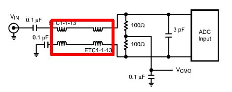
If it is one transformer,what problem do you happen? 

Thanks and Regards,

Kuramochi

  • Hi Kuramochi,

    A differential signal is recommended to drive the ADC input to maximize the dynamic performance. The balance of the differential signal is critical and influences the distortion performance, particularly the H2 distortion. At low frequencies, the ADT1-1WT+ gives very good single-ended to differential conversion with good balance, so 1 transformer is enough. At higher frequencies, the ADT1-1WT balance gets worse, so we replace the network with a cascade of 2x ETC1-1-13 (now called MABA007159) transformers. This network provides a wide bandwidth, and good balance at high frequencies. Only Using 1x MABA007159 does not have good enough balance.

    Regards, Josh

  • Hi Joshua-san,

    Thank you for your reply.

    Maybe, I understood.

    Is following connection of transformers correct ?

    Thanks and Regards,

    Kuramochi