This thread has been locked.

If you have a related question, please click the "Ask a related question" button in the top right corner. The newly created question will be automatically linked to this question.

ADS1258 in autoscan mode, first conversion appears to not be "chopping" ?

Other Parts Discussed in Thread: ADS1258


I am reading 16 pressure sensors (flexiforce) with this chip. I use all 16 of the single-ended channels for this.

It appears that the first of the auto-scanned conversions does not get "chopped" correctly.

I have "fixed" the problem by inserting an initial dummy conversion of the DIFF0 channel, and discarding the result. Works, but hardly ideal. Am I doing something wrong?

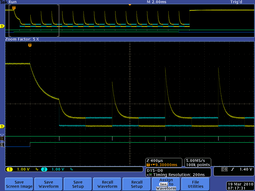
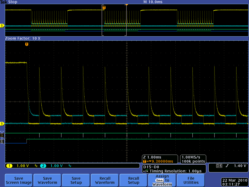
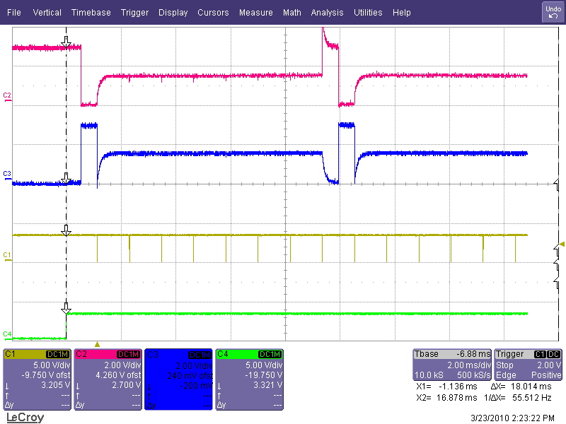
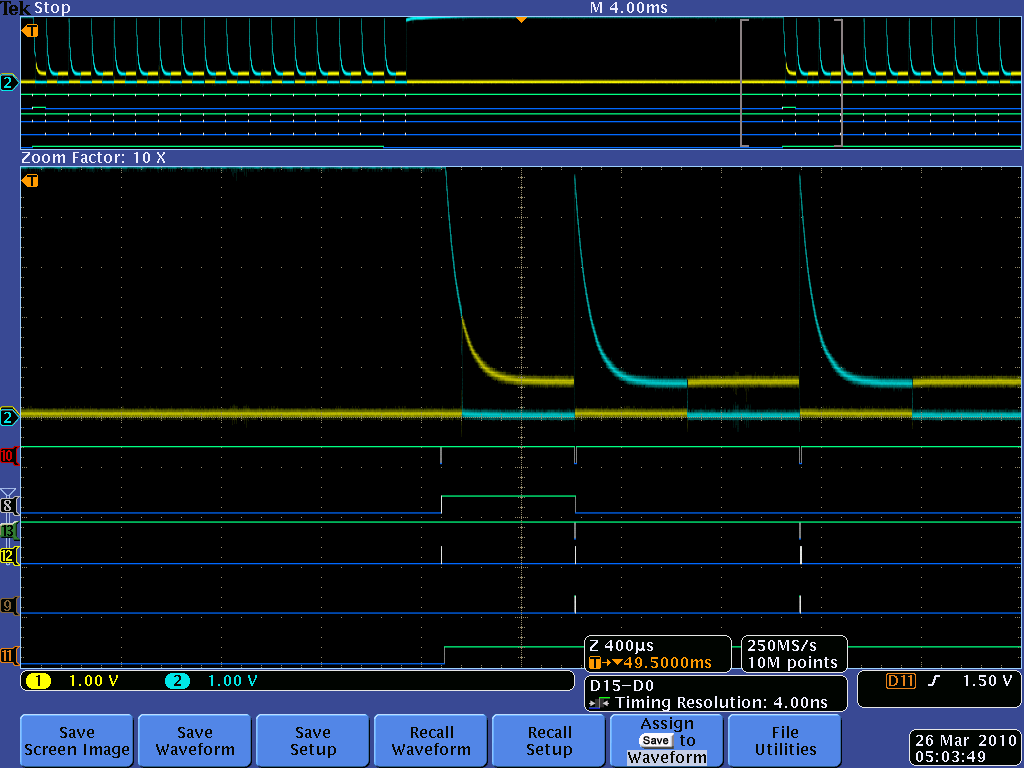
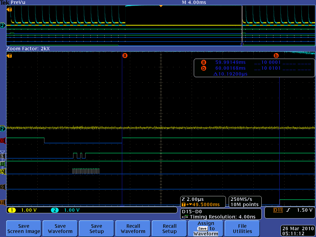
Attached is a scope picture showing what's happening. The bottom-most line, marked "8", is START. Above it, marked "9", is the DATA_READY signal. Yellow and blue are the positive and negative signals to be converted. This image is after the "fix", so the channel not being chopped is DIFF0. The subsequent channels are AIN0 - AIN15.

If more details will help, just ask.

Confused,

Brian


  • Brian, 

    I have a few questions about your setup and communication - 

    - When are you initializing CHOP? 

    - Does this happen every time START goes high? 

    - The Pulse Convert Command is used for a one time convert and reading. You probably would not want to use it in your application as you are converting all 16 channels of data and reading them back. However, I was wondering if you have ever tried using the Pulse Convert Command to see if the first reading is valid for you?

    - Can we see a scope picture of the behavior without the ''fix'' implemented? 


    Regards,

    Tony Calabria

  • Thanks for the quick reply.

    - When are you initializing CHOP? 

    At startup, I write and then read back all registers, prior to starting any conversion.


    - Does this happen every time START goes high? 

    Yes


    - The Pulse Convert Command is used for a one time convert and reading. You probably would not want to use it in your application as you are converting all 16 channels of data and reading them back. However, I was wondering if you have ever tried using the Pulse Convert Command to see if the first reading is valid for you?

    No, have not tried Pulse Convert yet.


    - Can we see a scope picture of the behavior without the ''fix'' implemented? 

    Attached. Good point, in that trace, you really can't see that the chopping doesn't occur, since with the "fix", the two signals measured first are almost the same, and you can't see that they aren't being swapped. My bad. It's clearer in this shot.

    These are the register values used for this trace:

    static uint8_t reg_values[10] = { 0x0e, 0x72, 0x00, 0x00, 0xff, 0xff, 0x00, 0xff, 0x00, 0x8b };


  • Brian, 

    I powered up the ADS1258 here and saw the behavior when I tried to copy your procedure. See below: 

    Red - MUXoutP

    Blue - MUXoutN

    Yellow - /DRDY

    Green - START

    In the scope picture I have a 3V input connected to AIN0 and nothing connected to the other analog inputs. I then Select to have the ADC in autoscan mode and select channels Ain0 - Ain7. When I bring START high I see that I do not have an issue with the first sample chopping.

    Note that I am not writing anything to any of the registers during my acquisitions. Are you writing anything to the part during your first acquisition? Utilizing the WREG command? 

    Regards,

    Tony Calabria

  • Thanks Tony - we are getting close to the answer now!

    I know what makes the difference between chopping occuring properly on the first acquisition, and not.

    The difference is a WREG operation immediately prior to (but BEFORE) START assertion.

    Old code (producing my scope pictures above) : Timer fires, I send a WREG SPI transaction, re-asserting the value in MUXSG0 (this forces the next set of conversions to begin at the highest priority channel; no other purpose). Once I get the interrupt telling me that the SPI receive has completed, I immediately assert START. Chopping is missing on first acquisition.

    New code : Timer fires, I assert START. *After* collecting my 16 samples, I send the WREG command re-asserting MUXSG0 (for the same reason). Chopping occurs properly on first acquisition.

    So it appears that there is some (possibly very short) time period required, after a WREG, before START assertion ?

    I have a solid work-around now, at any rate. Thanks for your consideration.

  • Joseph Wu, did you have something to add? I don't know what your "verification" is intended to mean.

    The issue is not resolved, if that's what you are implying. I do have a workaround, but that's not the same thing, is it?

    regards,

    Brian

  • Brian,

    Sorry about that. I thought that we'd identified where the problem was coming from.

    At first, I thought that the pulling the START high during the write would cause the problem. In the interpretation of the command in the ADS1258 verilog code it looked like there may have been a reset state between the command to the write of the register (within the byte), but I'm not sure this is the case anymore. However, I do think there is something similar to that going on, but it may take some time to dig through the code to find it.

    Regardless, I've unchecked the verify answer box.

    Joseph Wu

  • No worries Joseph.

    It may help you to know that I am using the Cortex M3 ARM processor, and using DMA to transfer the SPI data. In the situation where I see the chop not occurring on the first acquisition, I raise START in the SPI receive's DMA transfer-complete interrupt (as soon as the hardware receives those two bytes). This is going to be very close in time to the WREG SPI command completing - after, but very very close.

    The two bytes I send are [ 0x64 0xFF ], asserting 0xFF to MUXSG0. I ignore the reply data. Doing this at the end of my cycle instead of at the beginning makes the problem disappear, and the first acquisition chops normally.

    regards,

    Brian

  • Brian, 

    I understand that you have a work around, but we would like to look into this some more from our end. Is there any way you can get a scope picture without the fix showing the DIN, START, /DRDY and SCLK signals. I want to see your timing relationship between when you write to the MUXSG0 register to when START is brought high. 

    Also, have you tried just putting a short delay from when you finish writing to the MUXSG0 register to bringing START high? 

    Thanks,

    Tony Calabria 

  • Certainly sir! And thanks for the great support, by the way.

    I have not tried inserting a delay between MUXSG0 write-reg, and START assert (except to do it at end-of-cycle, as mentioned earlier).

    Signals:

    Analog, yellow/blue = signal.

    Digitals (the markers are in the left column):

    'Red 10' is SPI slave-select.

    'Black 8' is SPI MOSI

    'Green 13' is DRDY.

    'Yellow 12' is SPI SCLK.

    'Brown 9' is SPI MISO.

    'Orange 11' is START.

    First picture shows the first few conversions of the cycle. Second picture zooms in to show the SPI details, and on that shot, I have used the A/B markers to measure from SPI slave-select deassert to START assert time - a bit over 10 microseconds.


  • Brett,

    Sorry for the delay. I have been in the process of trying to reproduce this in my lab but have not been able to get the timing to meet yours. I have notified the design team on this issue and we are going to use the final test board and program to see if we can reproduce this timing. It may not be until the end of this week or next week until we can test this. I will let you know what we find. 

    Regards,

    Tony Calabria