I am using an Arduino Uno and the ADS1298ECG-FE. I have managed to successfully read ECG data that is being generated by my ECG simulator. However, there are some things that still need to be ironed out.
I have attached the following images at the end:
(1) Channel 1 – V6
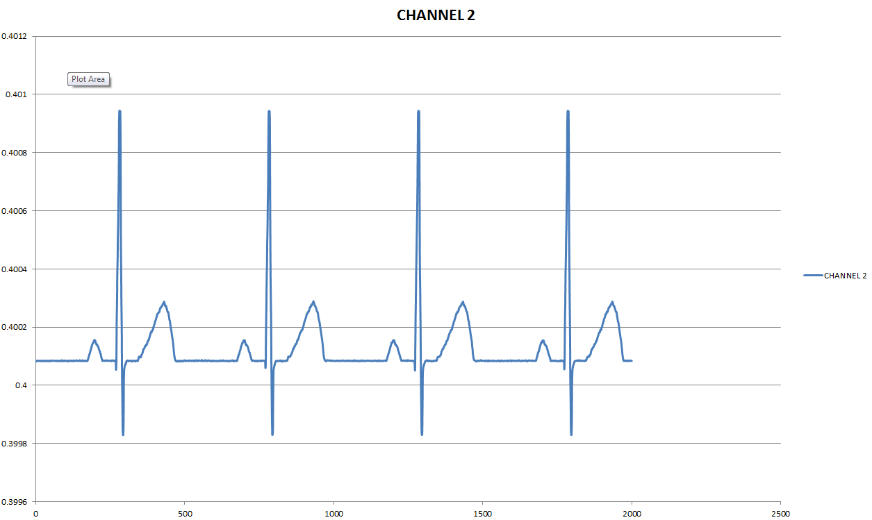
(2) Channel 2 – Lead I
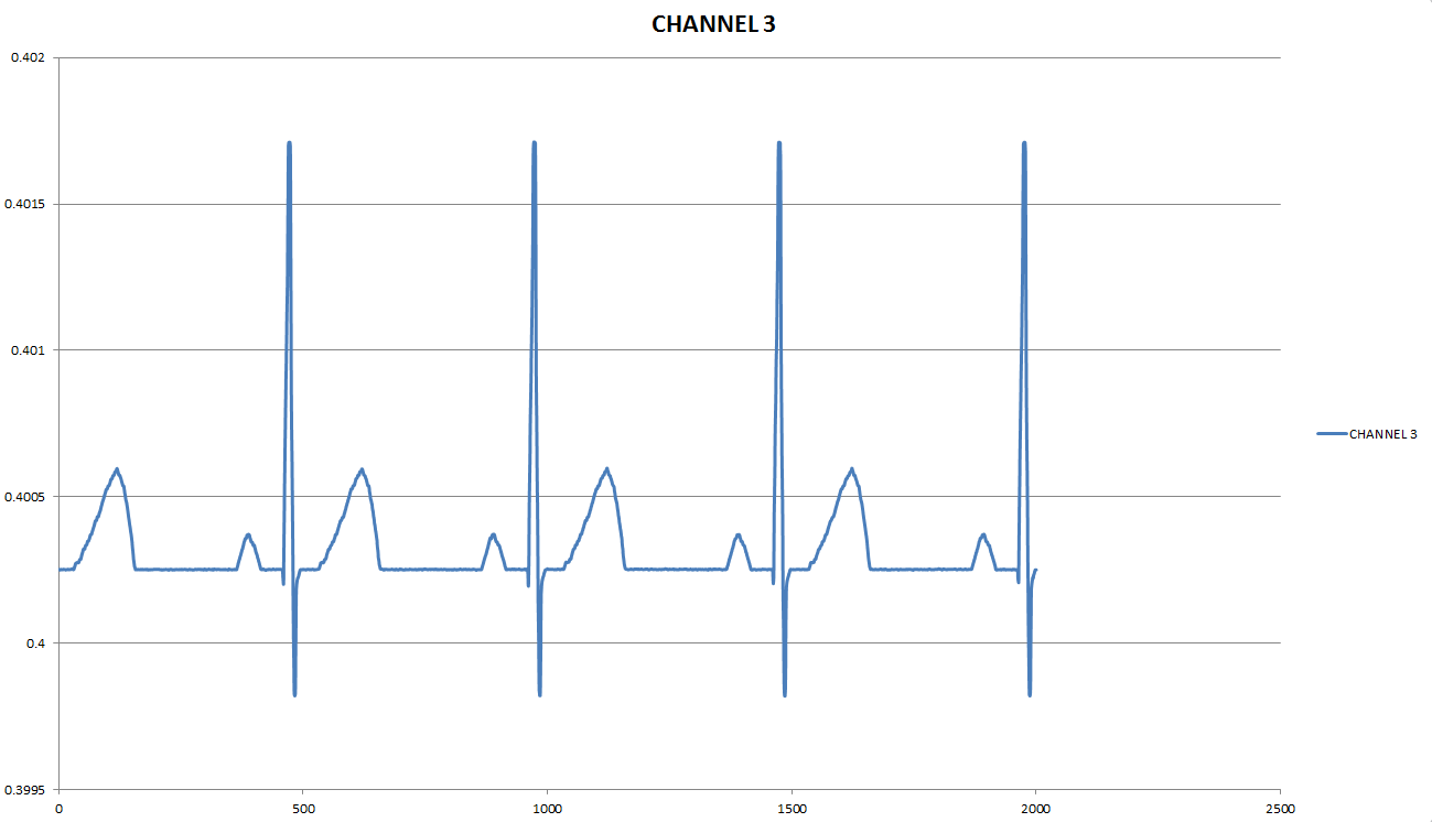
(3) Channel 3 – Lead II
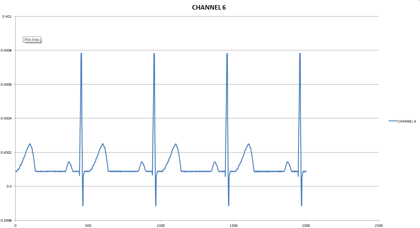
(4) Channel 6 – V4
(5) Channel 7 – V5
(6) Channel 8 – V1
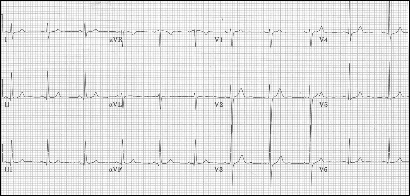
(7) 12-Lead ECG Waveforms
I am using the following ECG simulator to do my testing: http://www.stelec.com/internacional/english/simul/st-16.htm
It seems that Channel 7 (also Channel 4 and 5, waveform not shown) is not working correctly. I can’t imagine there is anything wrong with it that is different from the other channels. Is there any reason why they could be as such? It seems puzzling because everything else works fine. The following is the register settings for all registers:
void adsNormalElectrode_Copy()
{
  adc_wreg(0x00, 0x92);
  adc_wreg(0x01, 0x86);
  adc_wreg(0x02, 0x10);
  adc_wreg(0x03, 0xDC);
  adc_wreg(0x04, 0x03);
  adc_wreg(0x05, 0x00);
  adc_wreg(0x06, 0x00);
  adc_wreg(0x07, 0x00);
  adc_wreg(0x08, 0x00);
  adc_wreg(0x09, 0x00);
  adc_wreg(0x0A, 0x00);
  adc_wreg(0x0B, 0x00);
  adc_wreg(0x0C, 0x00);
  adc_wreg(0x0D, 0x00);
  adc_wreg(0x0E, 0x00);
  adc_wreg(0x0F, 0xFF);
  adc_wreg(0x10, 0x02);
  adc_wreg(0x11, 0x00);
  adc_wreg(0x12, 0xFF);
  adc_wreg(0x13, 0x06);
  adc_wreg(0x14, 0x00);
  adc_wreg(0x15, 0x00);
  adc_wreg(0x16, 0xF0);
  adc_wreg(0x17, 0x22);
  adc_wreg(0x18, 0x0A);
  adc_wreg(0x19, 0xE3);
}
Thank you for your time.
Regards,
Aslam