This thread has been locked.

If you have a related question, please click the "Ask a related question" button in the top right corner. The newly created question will be automatically linked to this question.

ads1234_noise_free_bits

Other Parts Discussed in Thread: ADS1234

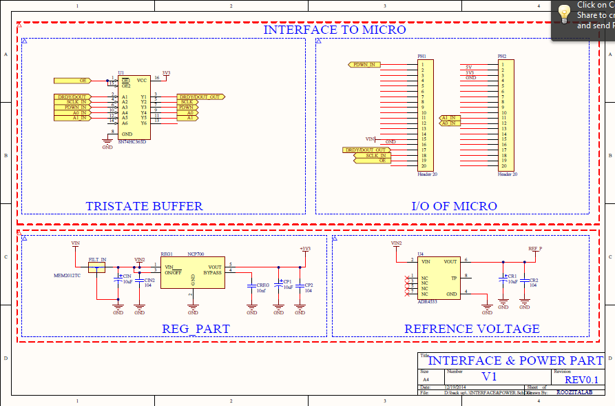
hello every one. i designed this sch and its board  and use battery for vin power supply .my power noise is less than 10mv. but i cant receive valid data more than 17 bits. and other bits changing continuously.pga is 1 and speed is 10sps. and here is my schematics thanks for helping me
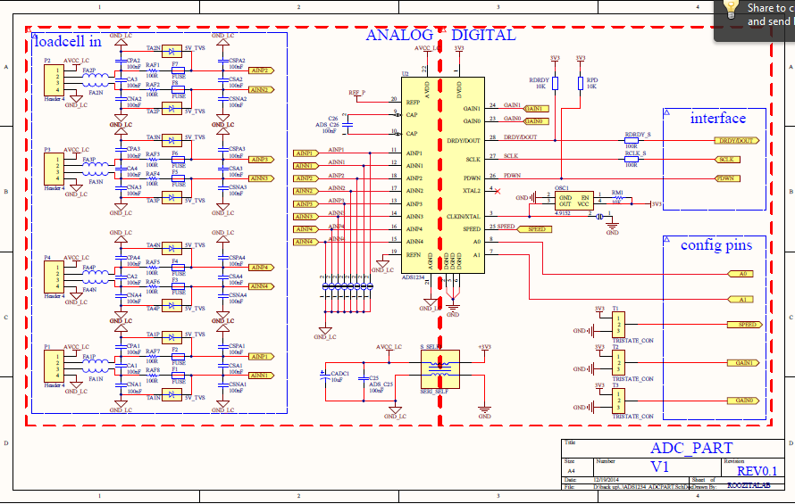
alireza roozitalab 

  • Hi Alireza,

    Is the 10mV supply noise you are describing on the analog supply?  What are you using for an input voltage?  Are you using a load cell?  If the source is noisy, then you will see noise on the output.  The best way to measure a load cell is to excite the load cell with the same voltage as you use for the reference so that the measurement is ratiometric.  Also the reference must not be more than 100mV above the supply.  Can you send me a series of some data as actual codes from the ADS1234?

    The best method to check the performance of your system is to short the inputs at the ADC biased to mid-supply to see if you are having board issues.  This is the first place to start.  If you get the datasheet noise performance, then you can check the rest of your system.

    Some general observations about your schematic.  The analog input differential cap should be at least 10 times greater than the common mode cap values.  Also, you should have a low impedance path between the analog and digital grounds.  Having an inductance in the ground path can be an issue which will violate the absolute maximum ratings should a transient event occur.  This would include board inductance.  The analog ground should be a plane and not just connection traces.

    Best regards,

    Bob B

  • hi bob

    thanks for your reply

    i use 150kg load cell for testing. or simple Wheatstone bridge circuit.

    10mv noise that i said is on the analog vdd

    loadcell (with no load) data is between

    0x7fba0a

    0x7fba40

    in using the Wheatstone bridge  i have one more bit true data

    the analog plane is here:

    but i have more than 100mv between reference and the supplay that i should check it

    thanks for helping me

  • Hi Alireza,

    You have isolated the analog input section, but it is difficult to know if there is any interaction between inputs or if the return currents for the analog are being forced into a more noisy area of the PCB.

    From your data I do have a concern as you are seeing nearly full-scale for a bridge that should be balanced.  A balanced bridge should see near 0 code.  A near full-scale reading at a gain of 1 is highly unusual.  A load cell ouput at full-scale may only be around 10mV and you are measuring closer to reference voltage value.

    First I would verify that all the input voltages and connections are correct.  If you still see issues, you should disconnect your load cell and short the inputs.  You should see a response closer to the datasheet noise numbers.  If you do not, then you have board issues that must be resolved first prior to connecting the load cells.

    Best regards,

    Bob B