This thread has been locked.

If you have a related question, please click the "Ask a related question" button in the top right corner. The newly created question will be automatically linked to this question.

ADS5409 analog input chain

Other Parts Discussed in Thread: ADS5409, ADS5402EVM

hello,
in the datasheet on the ADS5409 no recommendation on connection scheme of the input signal.

I use a scheme with double the transformers, the band of the input signal 70 - 270 MHz, AC - сupling.
The question is,

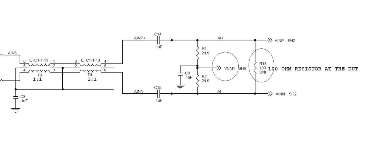
In ADS5402EVM board, there is an option to bias the common mode level of the analog signal. In which case this option is required?

In my application signal is always AC - сupling. I can not bias input signal to VCM?

The second question,

100 ohm termination resistor. I can not put it? In which case it is needed?
 

  • Hi Eugene

    The VCM1, VCM2 to VCMOUT connections shown were included in the board design to allow testing of devices that did not have the internal bias feature. For the ADS5409 you do not need to connect the center point of the 24.9 ohm resistors to the VCMOUT terminal of the ADC.

    I have confirmed that the 100 ohm resistors (R13 and R25) are not installed in the EVM. The pair of 24.9 ohm resistors provide the proper impedance termination at the output of the second balun. Apparently the board was designed to allow the 100 ohm secondary termination at the ADC inputs, but better performance was achieved without that resistor installed.

    I don't know the full history of this design, but will check with the expert when he is back from holiday. If you need to finalize your design soon I would keep the 100 ohm resistor in the circuit and then determine whether it should be installed during system evaluation.

    Best regards,

    Jim B

  • Thank you, Jim!

    Too little space on my board, but I will keep a 100 ohm resistor, as you suggest. 

    There is still a question. In my board 5 mm between the transformers. I can not determine the range, the between channels, to isolate them, to a level of - 80 dB.

    Best regards,

    Eugene.

  • Hi Eugene

    This is a challenging question to answer accurately.

    The best method would be to create a simulation model of the physical board design to estimate the crosstalk between the signal paths. A variety of industry tools are available to do this. You may need some support from the transformer vendors to help address any coupling between those devices.

    If that type of tool is not available to you then the best approach is to use good standard design practice and build a prototype to measure the performance, adjusting the design as necessary. One key best practice is to add good RF grounding (tie the ground pour to inner ground layers with multiple vias) in between the two signal paths.

    Best regards,

    Jim B

  • Hi Jim,
    I built a simple model in Hyperlynx, that shows crosstalk ~300 uV, which is not good. You will need to do something with it.

    Thank you for your answers,
    Best regards,
    Eugene.
  • Hi,

    Are you looking at crosstalk between the transformers from channel to channel?  On our EVM we usually deal with this with physical space between the input circuits of the two channels.  On the EVM we have to luxury of having room for it.    If you are very tight on space, you could consider using a single transformer on each input channel.  On an EVM we usually use a dual transformer (or balun) on each input channel because we are also using the transformer to do the single ended to differential conversion of a signal from a single ended signal generator,  The dual transformer results in less amplitude and phase imbalance between the two sides of the differential and such imbalance can introduce ripple on the VCM and degrade SFDR.   If you are not needing to do single ended to differential conversion then you would not need a dual transformer.  If you are doing SE to diff conversion, you may still not need dual transformer for an ADC with SFDR around 74dBFS anyway.     If you still have tight quarters and have crosstalk between your input circuits, you could consider a shielding can around each input circuit.  Another possible trick might be to angle the components slightly.  We had another EVM once that had coupling between the chip inductors used for an antialiasing filter and that was solved by not making the inductors pointing the same way.  Don't know if that would help with transformers.   Or - possibly put one input circuit on the top side of the EVM and the other on the bottom - but then there is the issue of keeping clock routed away from the inputs.

    Regards,

    Richard P.