Because of the Thanksgiving holiday in the U.S., TI E2E™ design support forum responses may be delayed from November 25 through December 2. Thank you for your patience.

This thread has been locked.

If you have a related question, please click the "Ask a related question" button in the top right corner. The newly created question will be automatically linked to this question.

TX810 - programmable TR/RX switch for ultrasound.

Other Parts Discussed in Thread: TX810

Hi,

I need to use a TX/RX  switch for my ultrasonic sensor. It looks like  TX810 is the right one. But before that i have couple doubts from the user guide. Link attached below. 

1. Figure 5 of the document shows recovery time with small input signal.

My understanding is that the input given is a combination of 0.25 Vpp followed by 140 Vpp.

The question that i have is, why is there an oscillation of 0.25V in the output  even after the input amplitude goes to  zero ( i.e after 0.25 micro second). 

Could someone pls explain me about this small signal at the output.?

2. Also can you please compare the Figure 6 with Figure 5 and ellaborate whats exactly going on at the output ?

Thanks in advance. 


  • Livingstone,

    Figure shows small signal sine wave mixed with an instaneous 1-cycle pulse. This is the input to the tx810. Therefore, the oscillation you see is a copy of the input signal, so this is expected. The purpose of this is to loosely replicate how quickly a small signal like an echo could valid after the TX event. The same experiment is done in Figure 6, except that there is no small signal component, therefore you only see the DC offset settling.

    Thanks,

    Chuck Smyth
  • Hi ,

    Thanks for the response. Initially i m trying tx/rx of my transducer with the following circuit design.

    We are using Capacitance based ultrasonic transducer (CMUT) to oscillate in 17MHz frequency for TX/RX. The  same transducer transmits and receives, while the transmitted signal is limited by the bridge diodes in the given circuit, and the received signal must be allowed to reach the transimpedance amplifier, so that i can be seen at the amplifier output. 

    During transmission the CMUT is excited using 60V DC and 5Vpp ac. During the receiving, the DC is still there but the AC signal goes off. The reflected received signal goes to the bridge diode circuit for further amplification. 

    In the below circuit, port P1 is for AC pulse, J1 is for DC bias, port P3 is the transducer that sends and receives the signal and port P2 is the output whose scopes are attached below . The second circuit is for powering up the amplifier. 

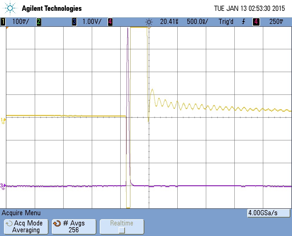
    Scope 1- with the transducer connected at P3 port

    channel 3 is transmitted signal, channel 1 is received signal at port P2.

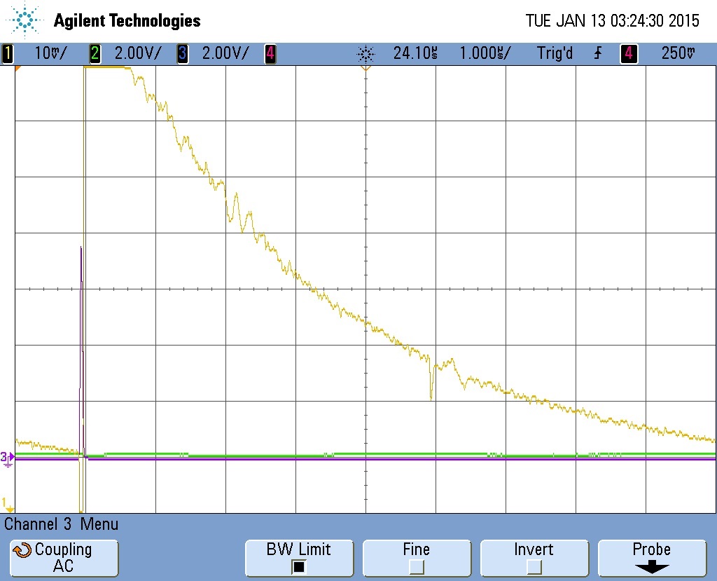
    Scope 2- without the transducer .

    channel 3 is transmitted signal, channel 1 is  signal at port P2.

    Both the above two scopes looks similar to the figure 5 & 6 of TX810 attached in my previous post.

    Does it means that the oscillating signal ,  that we are seeing from the scope 1 after the TX, is from the received signal (which is suppose to be a small signal)? 

    Thank you for the previous response.

    Regards

    Livingstone Arjunan

  • Hi 

    I have described my requirement below in detail. Kindly suggest the right component .

    i m using 2 ultrasonic transducer that is capacitive based one for transmitting and the other for receiving.

    The transmitting signal is AC pulse at 5Vpp  ,17MHz with DC bais of 60 V. This transmitted signal is received by the receiver transducer and its been given as an input to OPA 657 amplifier. And i am getting the output, which means the setup works fine. Below is the schematic of TX and RX mode.

    Now my intention is to do the same TX/RX using a single transducer whose transmitting signal has to be blocked or limited , before it reaches the op-amp's input and allow only the received signal to the same op-amp input. 
    So i m in need of a switching component which has capability to work as per my requirement. I found TX810 to be a right component for my project. Is there any better alternatives that suits my project needs or TX810 is the best option to go for?

    Thank you,

    Livingstone Arjunan

  •  

    Livingstone,


    The TX810 is designed specifiically to do exactly what you are talking about.  So, I understand your need.  The only issue is whether the performance, specifically the overload recovery, is good enough.  Is the input to the TX810 at 0V DC after the AC coupling cap?  What is the load at the output of the TX810?

    Thanks,

    Chuck Smyth

  • Also, the TX810 is the only solution that our Medical Ultrasound team has for this type of application. It's our only T/R Switch.
    Thanks, Chuck
  • Hello Chuck.
    Thank you for the response.

    The recovery seems to be okay for my project. I am expecting my signal to be between 2 micro - 4 microseconds.
    The capacitor C7 in the circuit that i have posted above blocks the DC from reaching the input of the TX810.

    In the above circuit the output of the diodes are connected to 1.1nF capacitor to reduce the recovery time, then 50 ohms resistor for impedance matching, then to the transimpedance amplifier that has feedback resistor 9.31k ohms and feedback capacitance of 1pF. The amplifier's output is connected to a oscilloscope or spectrum analyzer ((port P2).

    Before going ahead with TX810, i would like to know the ringing in output shown in scope 1 in my above post is due to the transmitted signal or the received signal. If its from the transmitted signal, then after replacing my diodes with TX810 , i believe i would be getting the transmitted signal only, when our signal of interest in received signal.

    It would be great if you could validate my circuit with the scope that i attached, so that i get to know whether i am in the right direction.
    Then i can replace my bridge diodes with standard TX810 .

    Thank you in advance.

    Livingstone
  • Hello guys,

    I am confused that how to connect an ultrasound probe to AFE58xx device. Is it possible to connect directly AFE58xx to an ultrasound probe????????? (I do not use transmit beamformer and high-pulser)

    Should I use Transmit/Receive switch?

    Please, some one help me