This thread has been locked.

If you have a related question, please click the "Ask a related question" button in the top right corner. The newly created question will be automatically linked to this question.

AFE4403 EVM DC signal unstable

Other Parts Discussed in Thread: AFE4403EVM

Hello,

I am testing the AFE4403EVM board and the IR and red signals look very noisy, making it hard to evaluate the SpO2 ratio, even after heavy filtering.

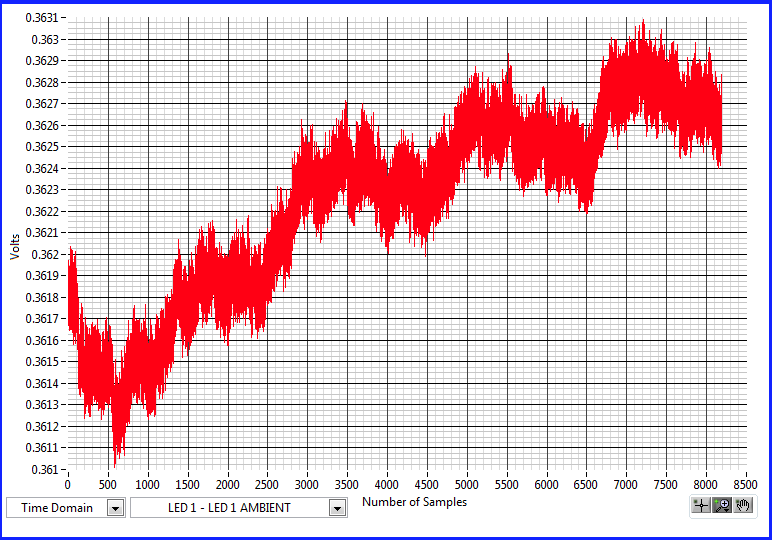
Can any one tell me if the signal below is what is expected?

The pictures on the Developement Guide look a lot nicer than that...

Signal: Red-Ambient, 500Hz sampling over 16 seconds.

Thanks,

Franck.

  • Thanks for the answer,

    By using the laptop, without power connected, the signal is cleaner but still very noisy.

    The 60Hz notch filtering does not seem to help a lot.

    After applying heavy filtering under excel (3Hz low pass FIR, 159 taps), some parts of the signal is usable for heart rate detection.

    However, I still have huge changes in the "DC" signal, making it often very difficult to get heart rate in some portions of the signal.

    This will be even more problematic to evaluate the SpO2 level...

    The graph below is the Red-Ambient after filtering with a 3Hz low pass filter, laptop disconnected from main.

    You can see the "DC" shifting in the first 7 seconds.


    Franck.

  • Franck,

    The AC portion of the PPG signal has a direct and exclusive relationship to the arterial pulse. The DC portion of the PPG signal is related to passage of light through several kinds of physiologically active tissue. Light transmission through these tissues will vary with temperature, hydration status, slow changes in arteriolar tone and many other factors. The AC pulsatile PPG signal has ~1% the amplitude of the DC component. Very slight changes in the value of the DC component will appear as large drift values for the AC signal. Drift of the AC signal is really a phenomenon related to small changes in the DC component that the AC signal rides on.

    The PPG signal drift is always observed unless there is high pass filtering or DAC based DC level correction that is applied to the signal acquired. If a LED/Photodiode pair heats or applies pressure to the skin this could result in increased PPG signal drift.

    You may need to apply baseline drift correction methods to remove the baseline wander.

    There may exist patented SpO2 estimation algorithms. There are numerous resources that can help you to develop your own algorithm. Refer to John Webster's Design of Pulse Oximeters. This book is an excellent resource to help you get started.

    http://books.google.com/books/about/Design_of_Pulse_Oximeters.html?id=eQh1DQtvowUC

  • Hi Praveen,

    I did some work SpO2 and pulse rate estimation about 15 years ago. At the time we didn't have integrated solution available and the filtering was done with OP Amp and discrets. The DC drift was compensated using counter and resistor ladder...
    I don't remember the DC drift being so fast making it easy to filter and compensate it.

    However, at the time we used transmissive sensors instead of the reflective supplied with the EVM.
    I guess that makes a big difference on the signal quality.

    I will get a transmissive sensor and run some fresh tests.

    Thanks for the help,
    Franck.