Hello TI support:
Now I am trying to connect an ADS1258 ADC converter to an Arduino Mega 2560 microcontroller. My goal is to apply a signal to ADS1258, connect ADS1258 to Arduino and Arduino to a computer, and read the time-variant voltage on the computer (the ADS1258 has been tested with MMB0 board as ADS1258-EVM-PDK, and it worked fine). The connection as follow:
#include <SPI.h>
const int DRDY=2;
const int DOUT=50;
const int DIN=51;
const int SCLK=52;
const int CS=53;
byte stat,data1,data2,data3;
void setup (void)
{
Serial.begin(9600);
pinMode(DRDY,INPUT);
pinMode(DOUT,INPUT);
pinMode(DIN,OUTPUT);
pinMode(SCLK,OUTPUT);
pinMode(CS,OUTPUT);
SPI.begin();
digitalWrite(CS,LOW);
digitalWrite(DIN,LOW);
}
void loop (void)
{
if (digitalRead(DRDY)==HIGH)
{
SPI.transfer(0B00110000);
stat = SPI.transfer(0x00);
data1 = SPI.transfer(0x00);
data2 = SPI.transfer(0x00);
data3 = SPI.transfer(0x00);
Serial.println();
Serial.println(data1, DEC);
Serial.println(data2, DEC);
Serial.println(data3, DEC);
}
}
241
31
157
241
31
157
241
31
157
241
31
157
Here are my questions:
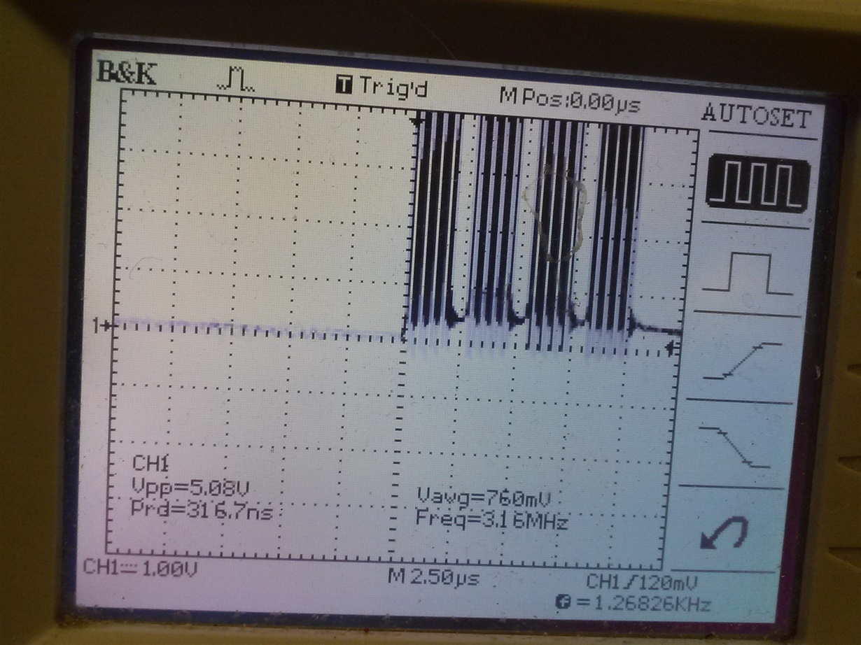
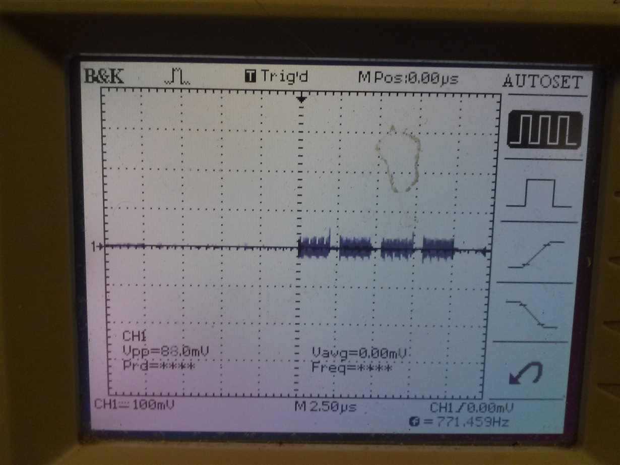
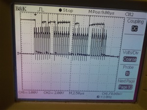
First, what are the timings to read data from DOUT? I measured SCLK on oscilloscope, and found that there are 4 packages of pulses (8 pulses each), which correspond to a 4-byte data reading period. The frequency of pulses in each package is about 4 MHz. However, I also need to know the correct delay to read data between packages and data reading periods, and add them into my code using delay() command. How should I get those timings correctly (and, according to my experience using ADS1258-EVM-PDK, the sampling rate is related to the number of channel being used)?
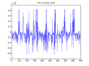
Second, after I get the timing correct, I can only get one bit data for diff0 channel in one 4-byte data reading period. However, to represent a voltage signal, I need a 24-bit voltage reading code (-8388608~8388607 as in ADS1258-EVM-PDK) from at least 24 4-byte data reading period. So, how should I assemble such a voltage-reading code?
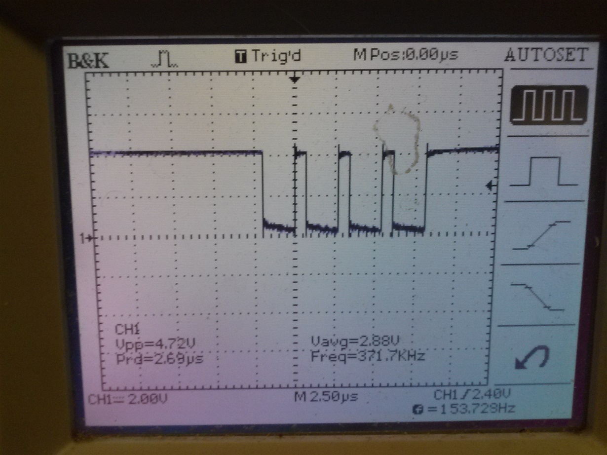
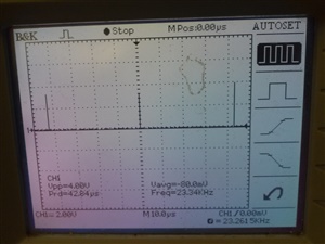
Also, I cannot see where DRDY is low during the test. Maybe the low-phase is too short so I cannot see it on the oscilloscope, or is there something wrong with my connecting or setting on it?
By the way, I refered to the post when connecting my boards: http://e2e.ti.com/support/data_converters/precision_data_converters/f/73/p/172252/640668, but it does not contain much code or explain my questions. Sorry I am relatively new to ADC converter and microcontroller...
Thank you!


