This thread has been locked.
If you have a related question, please click the "Ask a related question" button in the top right corner. The newly created question will be automatically linked to this question.
DEAR. ALL
Could help me
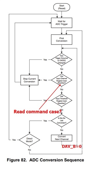
At the point of DAV_B=0 what recognized red column, does it take 1 usec for LOW of DAV_B pin?
How does ADC work out at the point of Read command case? or at the point of command registration which can read ADCn_data_register just ahead of DAV_B = 0?
Howdy Henry,
I'm assuming the above question is directed towards 'auto' mode, as in 'direct' mode the DAV pin stays active low until the ADC Data Register is read. In auto mode, a pulse of 1us (low) appears on the DAV pin to signify that new data is available.
In the above ADC Conversion sequence the DAV pin doesn't assert low until all active channels are converted. The DAV pin asserts low when the last channel is converted, this can be seen in the image you posted above in the "Is this the Last Conversion?". If it is the last channel being converted the part issues the 1us DAV pulse, then repeats the conversion sequence.
Once the DAV is read as 'low' the user can then readback the ADC Data Register for any enabled ADC channel.
Please let me know if this answers your questions.
Best Regards,
Matt
Hello Henry,
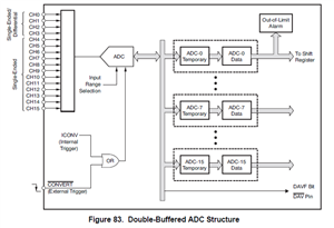
The ADC Register structure follows a Double-Buffered ADC Structure. This is displayed in the image below, but also in page 31 of the AMC7812 DS. As you can see in the image below the ADC channels have two output buffer registers, one is a temporary register and the other is the Data Register.
When in 'auto' mode, when the conversion of an individual channel is completed, the data is immediately transferred into the corresponding ADC-n temporary register. Only after the last channel conversion completes that all data in the ADC-n TMPRY Registers are simultaneously transferred into the corresponding ADC-n-Data Register. All ADC-n-Data Registers are not updated until this data transfer is complete. After the registers are successfully latched a 1us DAV pulse is sent to signify that new data is available for read.
If a read operation is performed before the ADC-n-Data Registers update the user will read ADC-n-Data results from the previous conversion, not from the current conversion.
To increase or decrease the conversion rate set the CONV-RATE-1 and CONV-RATE-0 bits of register 4Dh. This information is located on page 67 of the DS, as well as Table 18 of the DS.
Best Regards,
Matt