This thread has been locked.

If you have a related question, please click the "Ask a related question" button in the top right corner. The newly created question will be automatically linked to this question.

ADS8319 Daisy Chain Mode Without Busy Indicator

Other Parts Discussed in Thread: ADS8319, OPA320

Hello,

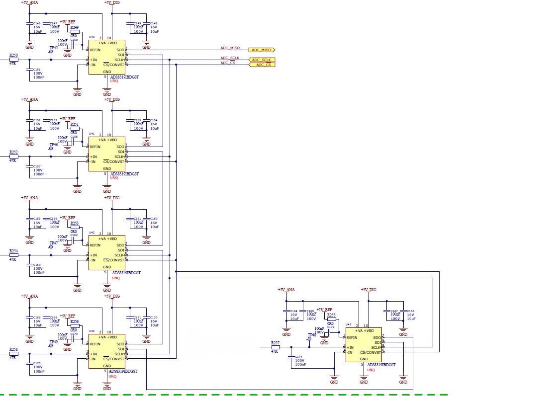
My project is proposing using 5 ADS8319 devices in "Daisy Chain Mode Without Busy Indicator".

We've never used these devices before and I would like to know if it is a reasonable solution to daisy chain 5 together, and if there are any constraints (hardware or software) that I am likely to encounter.

Regards,

Alan

  • Hi Alan,

    Sorry for the delay in my response. An obvious issue might be the switching (capacitive) load on the host IO pins driving SCLK and CONVST - you have 5 ADCs with their corresponding SCLK and CONVST pins shorted together and switching at relatively high speed (33MHz max on SCLK). The lumped cap load consists of the parasitic caps of the driver output pin, the ADC input pin and the trace connecting the two. According to the ADS8319 IBIS model, the input pins have about 0.8pF each for a total of about 4pF for 5 pins. Using 10mil wide traces on 5mil thick FR-4 with 1oz copper produces about 3.5pF/inch. Including the driver, the estimated load would be between 10 - 20pF that has to switch by 3.3V every 30ns. This translates to a source (IOL) or sink current (IOH) of about 2.2mA (=20pF * 3.3V/30ns). If the host digital output pins cannot support these minimum current levels, it would be a good idea to insert buffers.

    Best Regards,
    Harsha
  • Hello Harsha,

    Many thanks for the reply - it is much appreciated. I've added the proposed circuit (I hope it shows up OK). I think it looks OK but I'd be really grateful if you could confirm that it looks OK.

    Kind regards,

    Alan

    Hello Harsha,

    Many thanks for the reply.

  • Hi Alan,

    There are a couple of fundamental issues in the analog section of your design that can cause significant degradation of the accuracy of your ADCs.

    1) The reference voltage is the most critical signal for ADC accuracy. A reference voltage error of more than 1 part in 2^16 of the nominal Vref value (or 15ppm of 5V ~= 75uV in your case) during the conversion phase can cause output errors. Reference voltage error is a function of the output impedance of the reference voltage source and the load current through it, which spikes up dramatically while the ADC converts each bit (tens of mA). So the lower the load current and the lower the source impedance, the lower your error. In your case, there is a single REF voltage source driving 5 ADCs, all of which will be converting at the same time. In the interest of distributing the load current and keeping source impedance low, I would recommend inserting an op amp buffer at the REF input of each individual ADC. Here's a circuit I would recommend:

    Please ensure that the 10uF cap is placed as close to the ADC REFIN pin as possible to minimize trace inductance. The ESR is required for stability and its value is determined by the closed loop output impedance of the particular op amp that you select (the OPA320 in this case). A different op amp will probably require a different value of ESR.


    2) If you are planning on running the ADC at maximum sampling rate (500KSPS) then I'm afraid your input RC time constant is too big for the input to settle to a 16-bit level within the available 600ns acquisition window. This will also cause accuracy issues. I would recommend decreasing the value of the input capacitor to about 1nF and be sure to use a C0G/NP0 type for accuracy (has low voltage coefficient of capacitance). Once again it is important for your input sources to have low output impedance and for this reason, I would recommend inserting a buffer on each ADC input before the 47ohm resistor. 

    I would also encourage you to go through the following documents that explain the importance of low input source impedance for getting good performance from SAR ADCs:

    http://e2e.ti.com/blogs_/b/precisionhub/archive/2014/12/12/using-sar-adc-tina-models-much-ado-about-settling
    http://www.ti.com/lit/ug/tidu181/tidu181.pdf
    http://www.ti.com/lit/ug/tidu014/tidu014.pdf

    Best Regards,
    Harsha

  • Hi Harsha,

    Many thanks for the great reply. I'll talk it through with our hardware engineer.

    Kind regards,

    Alan